00195193-02 SG D4 FSE en (1).pdf - 第241页
C&P12 Placement Head Settings Light Barrier, Bottom Position S tudent Guide SIPLACE D4 (FSE) C&P12 Placement Head EN 09/2006 226 X Loosen the Z-axis e nd position stop screw. X Clamp a 15/100 mm feeler gauge betw…
C&P12 Placement Head
Setting the Z-Axis Upper Stop Settings
Student Guide SIPLACE D4 (FSE)
EN 09/2006 C&P12 Placement Head
225
Preconditions:
Before you begin adjustment work, check the belt tension and the correct installation of the belt lock at
the Z-axis.
9.5.6.3 Settings
X Switch off the machine. This setting can be performed directly at the machine.
X The star gauge for setting the Z limit stop is mounted on the C&P head in exactly the same way as
the zero point gauge for the star.
X Remove segment 1 and rotate the star until the gauge pin fits into the segment guidance.
X For better access to the Z-axis end position stop, unscrew the cable holder at one side and turn it to
the side. Then carefully push the flat ribbon cable to the side.
X Check whether the 5/100 mm feeler gauge passes easily (without resistance) between the Z-axis
end position stop and the tension jack (see diagram above).
X If this is not the case, you will need to adjust the Z-axis end position stop setting!
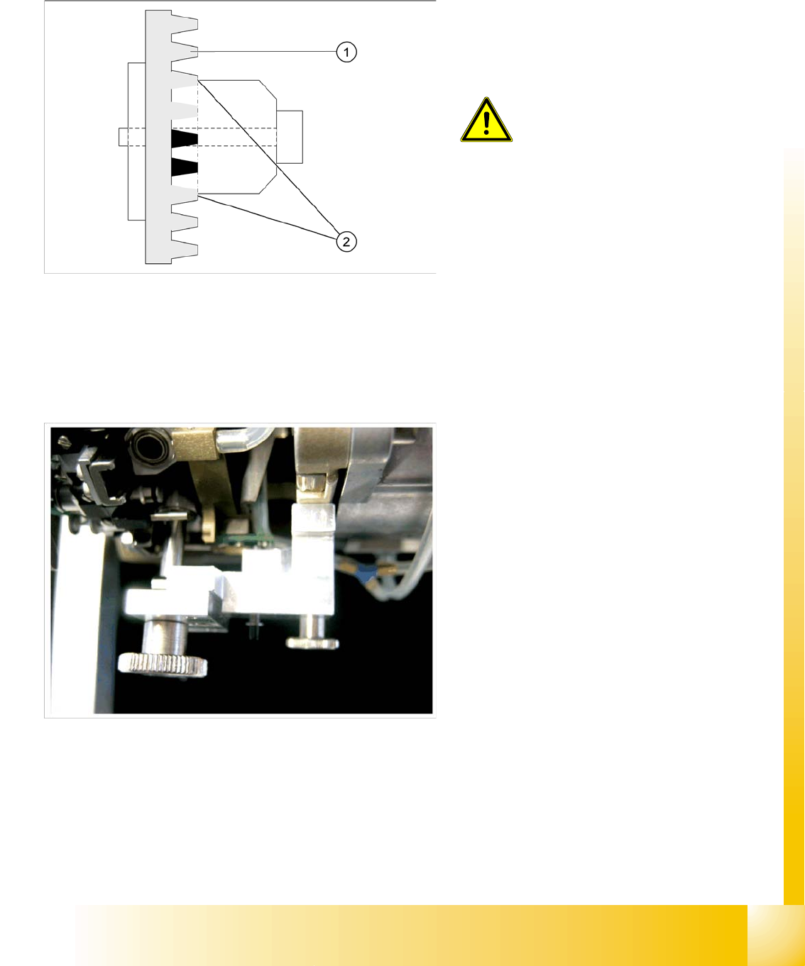
Legend:
1. Belt tension Z-Axis
2. Tension jack is positioned on the teeth at the
top and bottom
ATTENTION:
Make sure that both ends of the
tension jack lie on the teeth of the
toothed belt.
The star gauge ensures that the star is in the
correct position and that the Z-axis is pressed
upwards.
C&P12 Placement Head
Settings Light Barrier, Bottom Position
Student Guide SIPLACE D4 (FSE)
C&P12 Placement Head EN 09/2006
226
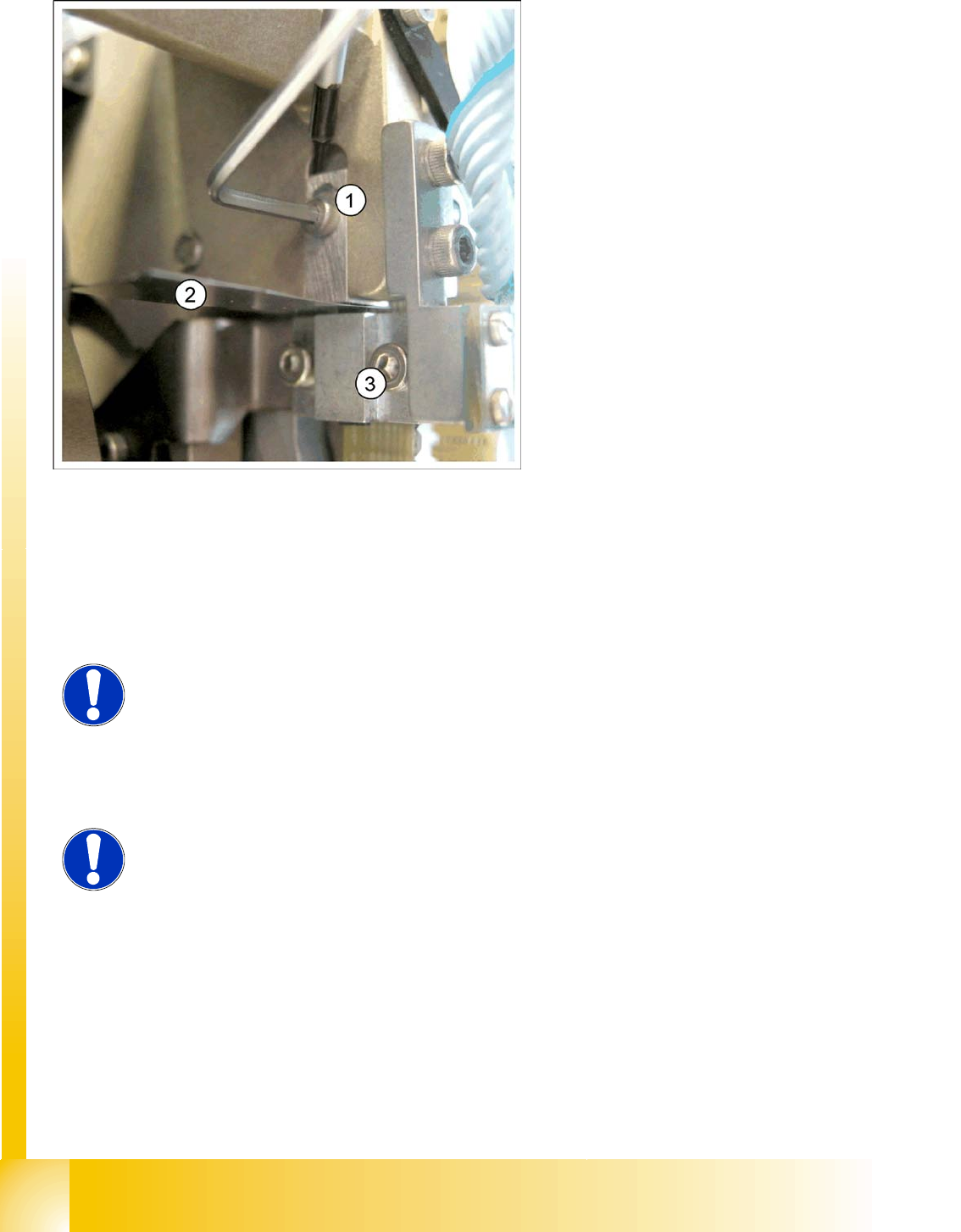
X Loosen the Z-axis end position stop screw.
X Clamp a 15/100 mm feeler gauge between the Z limit stop and the clamp. Gently press the Z-axis
end position stop downwards with the screwdriver and screw tight.
X It should now be more difficult to extract the 15/100 mm feeler gauge.
X Check again whether the 5/100 mm feeler gauge passes easily (without resistance) between the Z-
axis end position stop and the tension jack. If this is not the case, you will need to readjust the setting!
9.5.7 Light Barrier, Bottom Position
Legend:
1. Z-Limit stop
2. feeler gauge
3. Clamping device
NOTE:
When removing the gauge, make sure that the gauge pin is extracted first and
that then the star gauge is removed. If you do not observe this order, the gauge
could catch in the segments and damage these!
NOTE:
The light barrier is set with a test probe to a distance of 1.0 mm to the sleeve.
C&P12 Placement Head
Determining the Zero Point Correction for the Star Axis of the C&P Head Settings
Student Guide SIPLACE D4 (FSE)
EN 09/2006 C&P12 Placement Head
227
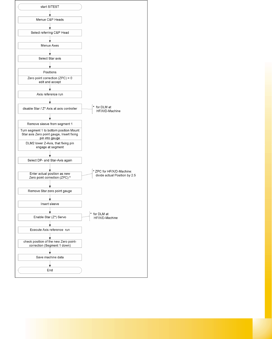
9.5.8 Determining the Zero Point Correction for the Star Axis of the C&P Head
During this process, make sure you adhere exactly
to the specified order and observe the comments
to each step!