00195193-02 SG D4 FSE en (1).pdf - 第243页
C&P12 Placement Head Settings Adjustment of Mechanical Position of Valve Drives S tudent Guide SIPLACE D4 (FSE) C&P12 Placement Head EN 09/2006 228 9.5.9 Adjustment of Mechani cal Position of V alve Drives 9.5.10…
C&P12 Placement Head
Determining the Zero Point Correction for the Star Axis of the C&P Head Settings
Student Guide SIPLACE D4 (FSE)
EN 09/2006 C&P12 Placement Head
227
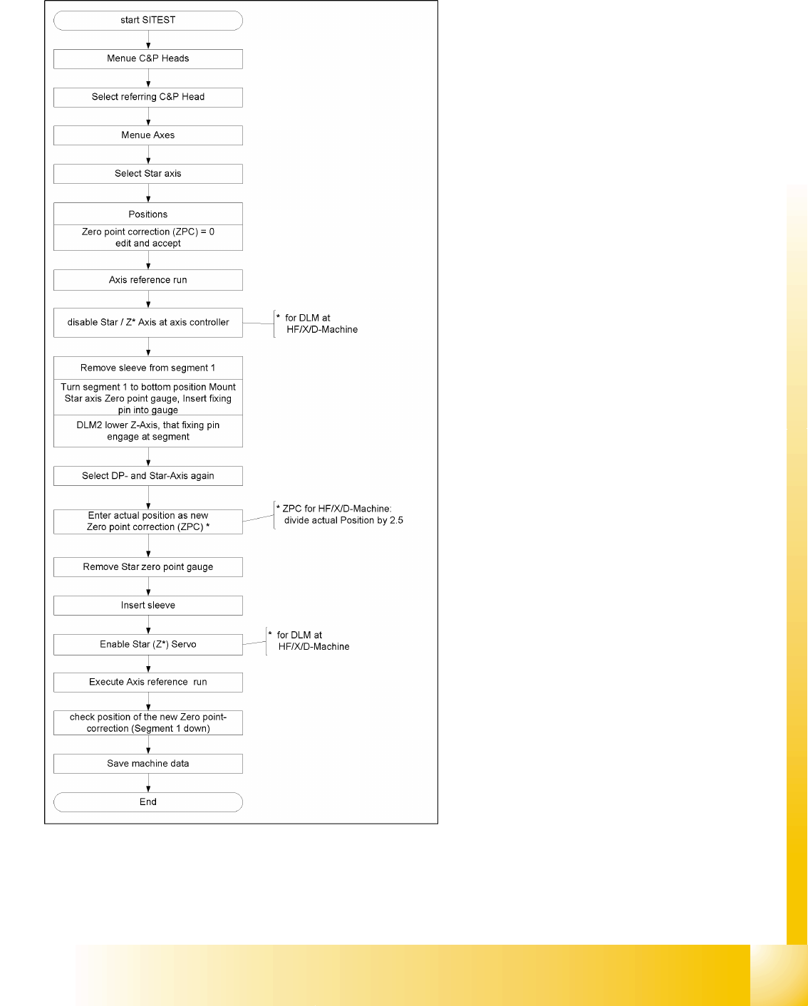
9.5.8 Determining the Zero Point Correction for the Star Axis of the C&P Head
During this process, make sure you adhere exactly
to the specified order and observe the comments
to each step!
C&P12 Placement Head
Settings Adjustment of Mechanical Position of Valve Drives
Student Guide SIPLACE D4 (FSE)
C&P12 Placement Head EN 09/2006
228
9.5.9 Adjustment of Mechanical Position of Valve Drives
9.5.10 Air Pressure Values
9.5.10.1 Tools and Devices
A set of slotted screw drivers
Compressed air testing device
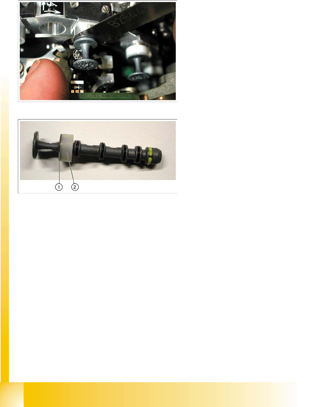
X Set the motor position of the valve positioning
drives "pickup/placement" and "reject" as
shown in the diagram.
X If the new valve plungers are used (s. diag. on
left) proceed as follows:
Take out one valve plunger and remove the
plastic bushing (2).
Insert the plunger without bushing and carry
out the following steps on this segment:
X Insert the distance gauge (0.2 mm) between
valve plunger and valve casing.
X Rotate the valve positioning drive 90 degrees
from its initial position. The excentric of the
valve drive will just touch the inner flange of
the valve.
X Fix the motor of the valve drive in this position.
X Remember to replace the tube on the valve
plunger.
C&P12 Placement Head
Air Pressure Values Settings
Student Guide SIPLACE D4 (FSE)
EN 09/2006 C&P12 Placement Head
229
9.5.10.2 Adjustment of Air Pressure Values
9.5.10.3 Adjustments of Air Pressure Values with the Compressed Air Testing Device
Adjust to the values of the table below:
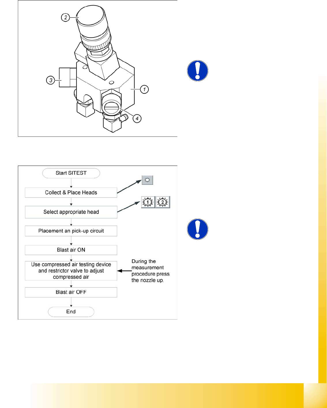
Legend:
1. Forced air unit
2. Solenoid valve for air kiss
3. Adjustment valve for the reject circuit
4. Adjustment valve for the pick - up / placement
circuit
NOTE:
Use a nozzle of type 914 to set the air
kiss. Please press in the spring from
the nozzle interface during the
measurement and read the value
from the display.
When setting the air kiss value with the
compressed air device and the adjustment valve,
observe the following:
X Press the nozzle upwards during the
measurement process!!
NOTE:
The air kiss values, which are shown
at the menu item
Measure pressure
on the screen of the station computer
in
single functions or in
the SITEST
program, do not correspond with the
air kiss values actually set at the
nozzle. They solely serve to check
that the forced air valve is functioning
correctly. Therefore, do not use the
values shown on the screen to set the
air kiss. Instead, use only the values
determined with the compressed air
testing device.