00195193-02 SG D4 FSE en (1).pdf - 第245页
C&P12 Placement Head Nozzle changer Other Mechanical Adjustments on the Star S tudent Guide SIPLACE D4 (FSE) C&P12 Placement Head EN 09/2006 230 Repeat these adjustments severa l times, as the pi ck - up / placem…
C&P12 Placement Head
Air Pressure Values Settings
Student Guide SIPLACE D4 (FSE)
EN 09/2006 C&P12 Placement Head
229
9.5.10.2 Adjustment of Air Pressure Values
9.5.10.3 Adjustments of Air Pressure Values with the Compressed Air Testing Device
Adjust to the values of the table below:
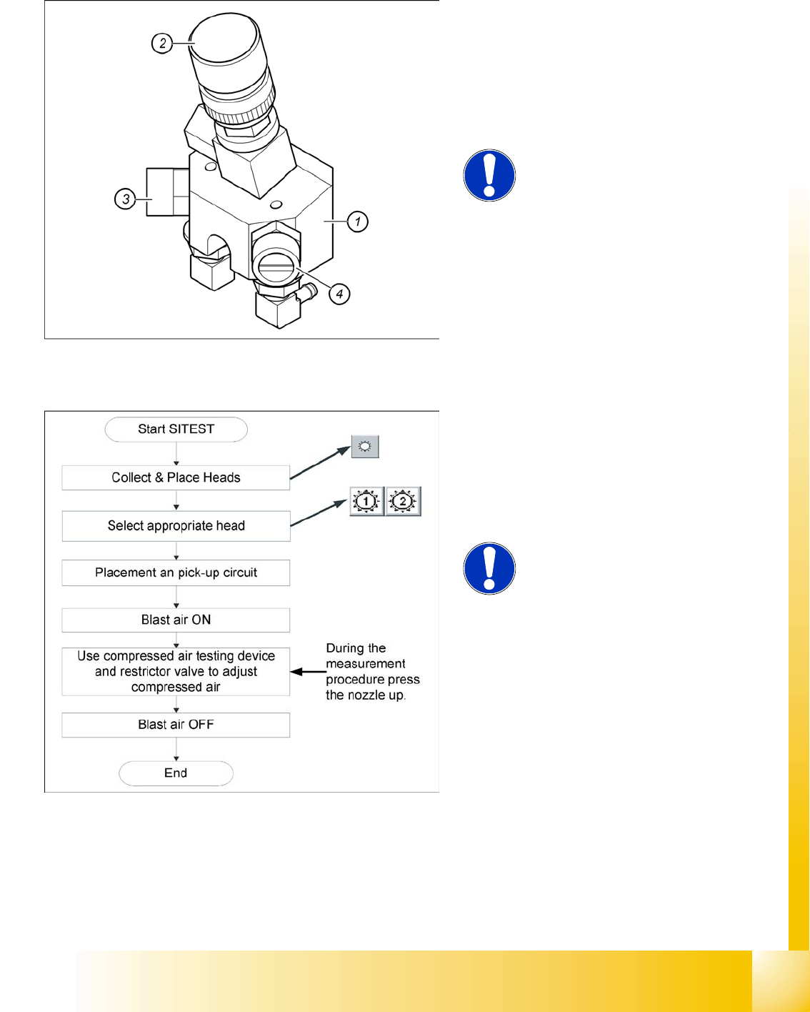
Legend:
1. Forced air unit
2. Solenoid valve for air kiss
3. Adjustment valve for the reject circuit
4. Adjustment valve for the pick - up / placement
circuit
NOTE:
Use a nozzle of type 914 to set the air
kiss. Please press in the spring from
the nozzle interface during the
measurement and read the value
from the display.
When setting the air kiss value with the
compressed air device and the adjustment valve,
observe the following:
X Press the nozzle upwards during the
measurement process!!
NOTE:
The air kiss values, which are shown
at the menu item
Measure pressure
on the screen of the station computer
in
single functions or in
the SITEST
program, do not correspond with the
air kiss values actually set at the
nozzle. They solely serve to check
that the forced air valve is functioning
correctly. Therefore, do not use the
values shown on the screen to set the
air kiss. Instead, use only the values
determined with the compressed air
testing device.

C&P12 Placement Head
Nozzle changer Other Mechanical Adjustments on the Star
Student Guide SIPLACE D4 (FSE)
C&P12 Placement Head EN 09/2006
230
Repeat these adjustments several times, as the pick - up / placement circuit are mutually dependent.
9.5.11 Other Mechanical Adjustments on the Star
Set the air kiss tube so that it overlaps the circular guide frame by 0.7 mm.
9.6 Nozzle changer
The installation of a nozzle changer (PPC) allows the C&P12 to be quickly and automatically equipped
with an optimum nozzle configuration after a job changeover and to be adjusted to the requirements of
the placement process.
9.6.1 Nozzle changer for 12 segment C&P head
The nozzle changer consists of at least one and up to five magazines, each of which is equipped with
up to twelve nozzle garages. The magazines are seated on a common support and each magazine is
centered using two parallel pins and fixed in place with a spring hook.
Air Pressure Values Set with compressed air testing
device
Measured at the nozzle
Displayed on the Monitor:
(Only in Pick - Up and Placement
Circuit)
pick - up / placement circuit 150 mbar (100 - 200 mbar) e.g.: 250 mbar
reject circuit (not used for
reject at HFand X machine)
250 mbar (200 - 300 mbar) The reject circuit does not have a
sensor
NOTE:
The two air kiss circuits are controlled via a single valve and therefore influence
one another mutually. However, two different adjustment valves (see items 3
and 4 in the diagram above) can be used to set the various pressures for each
circuit.
NOTE:
Make sure the measurement sensor hose is fitted tightly on the nozzle.
C&P12 Placement Head
Nozzle changer for 12 segment C&P head Nozzle changer
Student Guide SIPLACE D4 (FSE)
EN 09/2006 C&P12 Placement Head
231
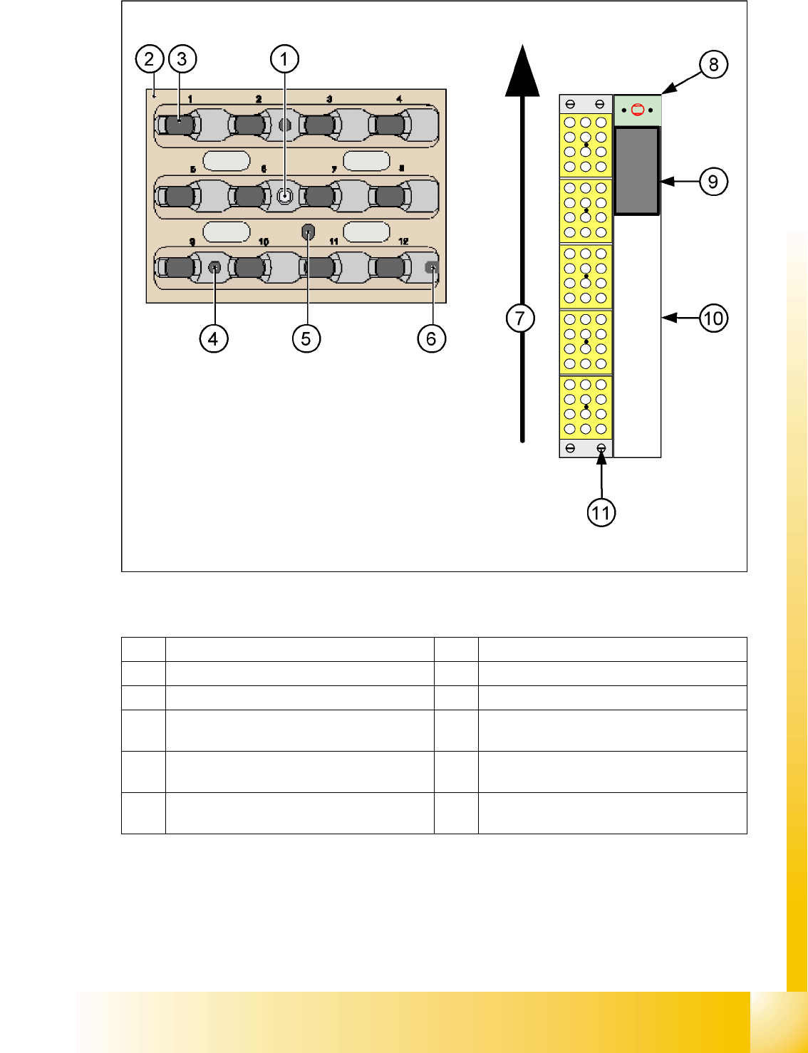
9.6 - 1: Nozzle changer and nozzle magazine for 12 segment C&P head
Legend
1 Calibration fiducial 7 Transport direction
2 Locking Plate 8 Nozzle reject device
3 Nozzle garage 9 Nozzle reject container
4 Hole for centering pin, for exact positioning of
magazine
10 Tape duct
5 Hole for driver pin, for opening and closing of
magazine
11 Fastening screws for nozzle changer (4x)
6 Slit for centering pin, for exact positioning of
magazine