00195193-02 SG D4 FSE en (1).pdf - 第251页
Component handling Overview Assembly S tudent Guide SIPLACE D4 (FSE) Component handling EN 09/2006 236 10.1.3 Assembly The trolley is easily moved and maneu vered. The handles can be swung up or down. The CO table has a …
Component handling
CO Changeover Table Construction (S Table) Overview
Student Guide SIPLACE D4 (FSE)
EN 09/2006 Component handling
235
10.1.2 CO Changeover Table Construction (S Table)
See also:
J 10.1 Overview [J 233]
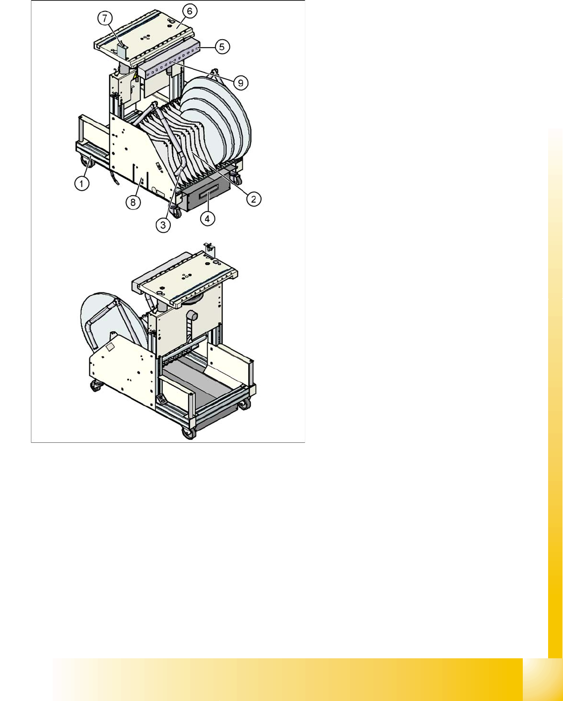
Legend:
1. flexible base
2. Tape reels container
3. Handles
4. Tape waste container
5. Communication unit; Splice recognition unit
option is installed below the communication
unit
6. Feeder table plate
7. Switch for lowering the CO table
8. Slot for set up lists on both sides
9. Voltage 30 V communication unit (yellow LED)
Component handling
Overview Assembly
Student Guide SIPLACE D4 (FSE)
Component handling EN 09/2006
236
10.1.3 Assembly
The trolley is easily moved and maneuvered.
The handles can be swung up or down.
The CO table has a maximum capacity of 12 locations for feeder modules with widths of 30 mm. These
feeder modules are mechanically centered on the table with centering pins and spherical calottes. The
bulkcase feeders are supplied with compressed air from a separate line.
A cable provides the interface connection to the machine. The power supply, communication and
emergency stop circuits are run via this cable. The compressed air supply for the bulkcase feeder
modules is also covered by this interface.
The communication unit supplies the feeder modules with the required voltages and control signals.
The tape reel container accepts tape reels up to a size of 19" (483 mm). The extractable waste tape
container is located on the underside of the flexible base. These waste tape clippings are taken down a
chute, into the waste container (which requires regular emptying).
See also:
J 10.1 Overview [J 233]
ATTENTION: Operational Safety
To operate the machine, all CO trolleys must be docked onto the machine. If
this is not the case, the machine will remain in emergency stop mode and the
placement process will be interrupted.
CAUTION:
Unused locations need to be occupied by a dummy feeder, to prevent access
to the machine at those points (risk of injury from reaching into the machine).
Component handling
Docking and Undocking the CO Changeover Table Overview
Student Guide SIPLACE D4 (FSE)
EN 09/2006 Component handling
237
10.1.4 Docking and Undocking the CO Changeover Table
Undocking the CO trolley
X Click in the
MAIN VIEW
menu, on the
STOP PROCESSING PCB icon.
.
The board currently being processed will be finished. After processing of this board has been
completed, the icons for the menu functions will be enabled.
X Click on the
SINGLE FUNCTIONS GANTRY
.
X Select
GANTRY FUNCTIONS.
.
X In this menu, click on the
GO TO SETUP POSITION
.
All placement heads are moved over the board conveyor, so that they can not be damaged during
CO trolley changeover.
X Open the protective hood above the required gantry.
X Open the cover flaps above the height adjustment button for the CO table plate.
X Press the button until the CO table plate has reached its end (top) position.
X Disconnect the CO trolley supply cable from the socket at the station.
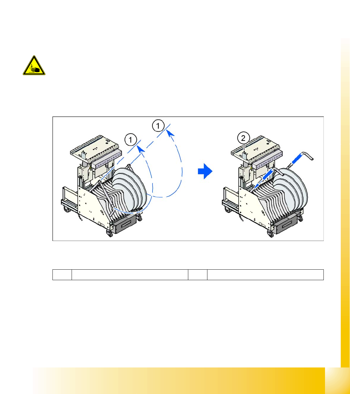
X Swivel both handles upwards (1).
10.1 - 2: CO trolley - swivel handles upwards
Legend
X Use both hands to pull the CO trolley out of the machine.
X Press the button to lower the CO table (2).
DANGER:
When raising the CO table, never reach into the gap between the feeder
modules and the empty tape duct.
1 Handle 2 Switch for lowering the CO table