00195193-02 SG D4 FSE en (1).pdf - 第256页
Component handling Optional Extension on the COT Component table Student Guide SIPLACE D4 (FSE) EN 09/2006 Component handling 241 X Unscrew the eyebolt from the CO trolley table. 10.2.2 Optional Exte nsion on the COT 10.…
Component handling
Component table Adjustment of the COT height
Student Guide SIPLACE D4 (FSE)
Component handling EN 09/2006
240
10.2 Component table
10.2.1 Adjustment of the COT height
10.2.1.1 Adjusting the CO Trolley to the Board Transport Height
10.2.1.2 Tools and Devices
The following tools and equipment are needed to adjust the height of the CO trolley:
Set of Allen keys, size 5
Eyebolt with M12 thread for raising the CO trolley table,
DIN 580 M12-St, article no. 00048350-xx
Leverage device for raising the CO trolley table, must be able to carry at least 80 kg
10.2.1.3 Adjusting the CO Trolley Height
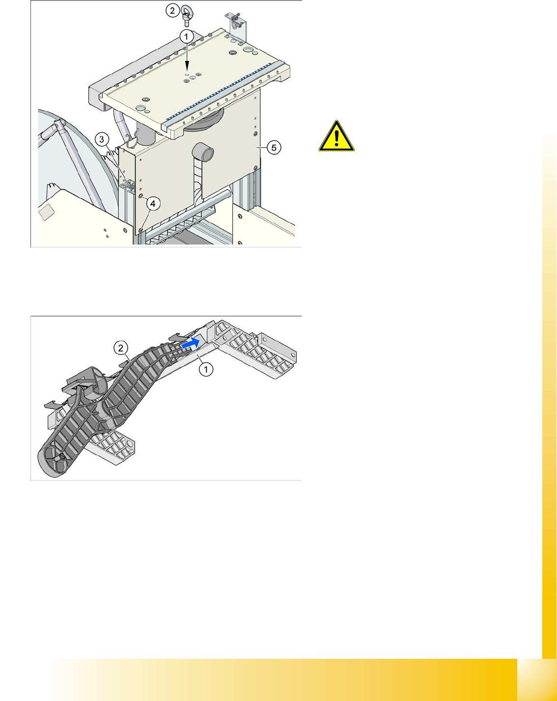
X Screw the eyebolt into the M12 hole provided (1) on the CO trolley table.
X Hook the leverage device onto the eyebolt (2).
X Tighten the rope of the leverage device.
X Loosen the 8 hexagon socket-head screws, M6x12 (4).
X Lift or lower the CO trolley table to the required height. Make sure that the hole for the required height
in the bridge (5) is level with the top hole in the vertical profile bar (3).
X Fasten the bridge (5) to the vertical profile bar (3) with the 8 hexagon socket-head screws M6x12 (4).
Legend:
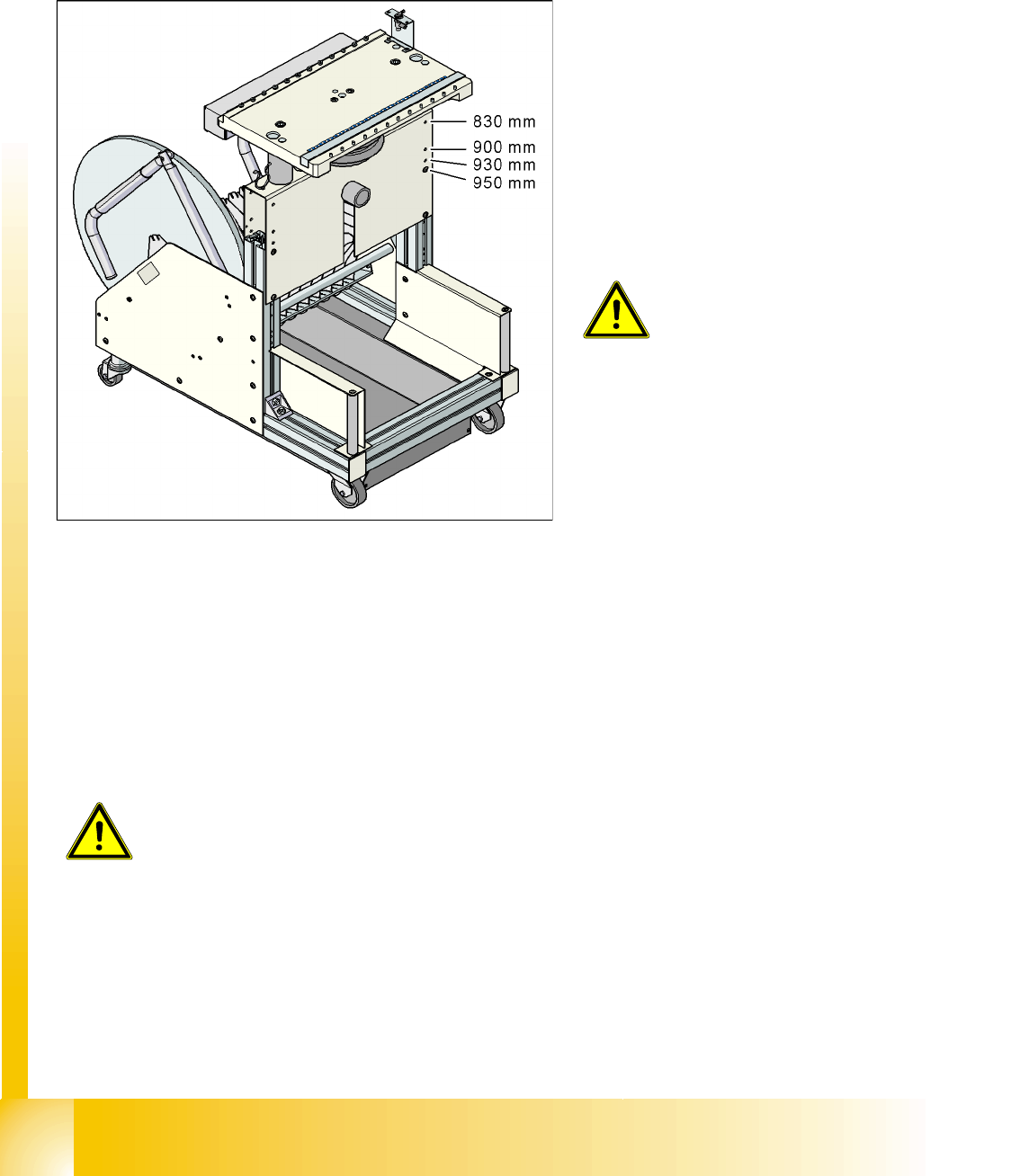
Holes drilled for board transport heights 830 -
950 mm in the guidance bars
The CO trolley for the S feeder modules can be
easily and quickly adjusted to the following board
transport heights:
830 mm ±15 mm standard height
900 mm ±15 mm SMEMA height
930 mm ±15 mm SMEMA height
950 mm ±15 mm SMEMA height
WARNING:
The CO trolley height may only be set
by SIEMENS technicians or other
qualified and officially authorized
(certified) personnel.
X Observe the applicable accident
prevention regulations.
X Remove all feeder modules from
the CO table plate, before you
adjust the height of the CO table.
WARNING:
Lift all feeder modules off the CO trolley table plate.
Component handling
Optional Extension on the COT Component table
Student Guide SIPLACE D4 (FSE)
EN 09/2006 Component handling
241
X Unscrew the eyebolt from the CO trolley table.
10.2.2 Optional Extension on the COT
10.2.2.1 Holder for the Middle Tape Reel on 3 x 8 mm S Feeder Modules
The following is needed for the middle tape reel:
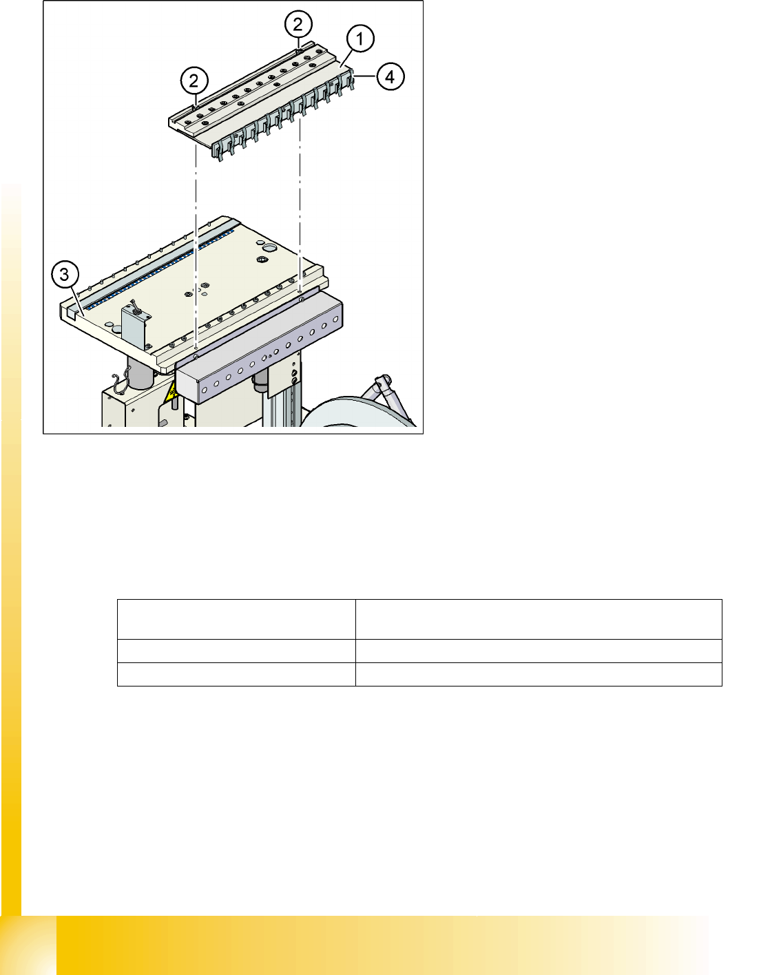
An adapter plate to hold the tape reel holder (1) and
One tape reel holder for every two feeder modules (2).
The adapter plate is fixed with four cylinder screws to the CO trolley, while the tape reel holder is plugged
into the square openings in the adapter plate.
Legend:
1. M12 hole drilled for eyebolt
2. Eyebolt DIN 580 M12-St
3. Vertical profile bar
4. 8 x hexagon socket-head screw SN 62355,
M6x12
5. Bridge
CAUTION:
Always use the fit-up aid (screwed
eyelet) to fix the table plate,
irrespective of whether you want to
raise or lower the CO trolley.
Legend:
1. Adapter plate
2. Tape reel holder
Feeder modules of type 3 x 8 mm-S transport
components in three feeder tracks to the pickup
position. The tape reels on the two outer tracks are
located between the divider sheets in the tape
container. The middle tape reel is located above
the two tape reels for the outer tracks.
Component handling
Component table Optional Extension on the COT
Student Guide SIPLACE D4 (FSE)
Component handling EN 09/2006
242
10.2.2.2 Compressed Air Supply for Bulkcase Feeders
10.2.2.3 External Power Supply
To keep the time for setup changeovers to a minimum, the CO trolleys can be set up at an external setup
location. The feeder module functions and settings can also be checked there as part of the preparations
for operation. An external power supply unit is available for this purpose. The CO trolley is supplied with
the required operating voltage and compressed air via a supply cable.
Technical data
The unit is supplied with a European standard line cable, a US standard line cable and a connection
cable for linking the voltage supply to the CO trolley.
Bulkcase feeders require compressed air. The
optional compressed air supply for bulkcase
feeders is available for this purpose.
Installation is easy. The compressed air distributor
(1) is fixed with two screws (2) to the CO table (3).
The compressed air distributor is then connected
to the CO trolley compressed air supply. At the
back of the compressed air distributor, there is a
row of brackets (4). These fix the bulkcase feeder
modules to the CO table, ensuring optimum
compressed air supply.
Legend:
1. Compressed air distributor
2. 2 x screw DIN 912, M8x20
3. Feeder table plate
4. Brackets
Line voltage 230 V~ ±5 %
120 V~ ±5 %
Compressed air connection max. 1.0 MPa (10 bar)
Output pressure Adjustable via valve