00195193-02 SG D4 FSE en (1).pdf - 第257页
Component handling Component table Optional Extension on the COT S tudent Guide SIPLACE D4 (FSE) Component handling EN 09/2006 242 10.2.2.2 Compressed Air Supply for Bulkcase Feeders 10.2.2.3 External Power Supply To kee…
Component handling
Optional Extension on the COT Component table
Student Guide SIPLACE D4 (FSE)
EN 09/2006 Component handling
241
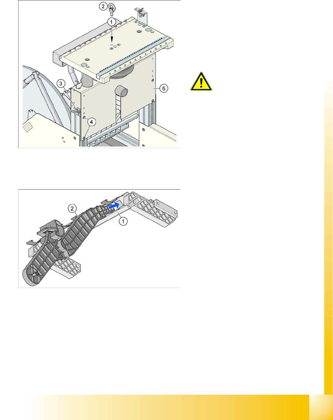
X Unscrew the eyebolt from the CO trolley table.
10.2.2 Optional Extension on the COT
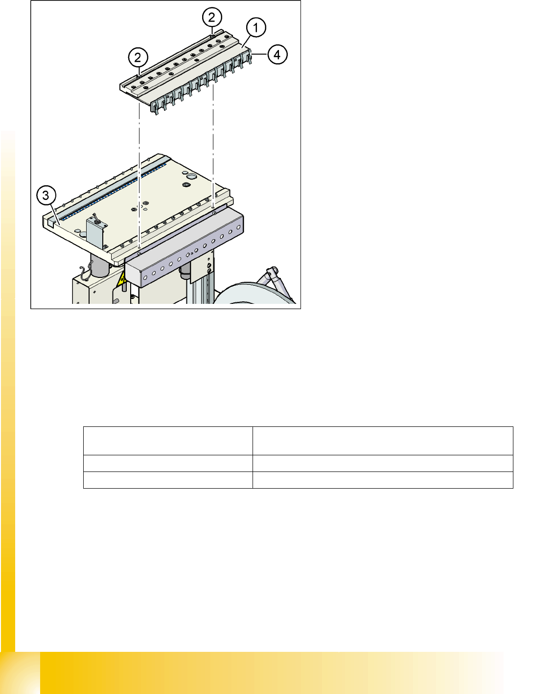
10.2.2.1 Holder for the Middle Tape Reel on 3 x 8 mm S Feeder Modules
The following is needed for the middle tape reel:
An adapter plate to hold the tape reel holder (1) and
One tape reel holder for every two feeder modules (2).
The adapter plate is fixed with four cylinder screws to the CO trolley, while the tape reel holder is plugged
into the square openings in the adapter plate.
Legend:
1. M12 hole drilled for eyebolt
2. Eyebolt DIN 580 M12-St
3. Vertical profile bar
4. 8 x hexagon socket-head screw SN 62355,
M6x12
5. Bridge
CAUTION:
Always use the fit-up aid (screwed
eyelet) to fix the table plate,
irrespective of whether you want to
raise or lower the CO trolley.
Legend:
1. Adapter plate
2. Tape reel holder
Feeder modules of type 3 x 8 mm-S transport
components in three feeder tracks to the pickup
position. The tape reels on the two outer tracks are
located between the divider sheets in the tape
container. The middle tape reel is located above
the two tape reels for the outer tracks.
Component handling
Component table Optional Extension on the COT
Student Guide SIPLACE D4 (FSE)
Component handling EN 09/2006
242
10.2.2.2 Compressed Air Supply for Bulkcase Feeders
10.2.2.3 External Power Supply
To keep the time for setup changeovers to a minimum, the CO trolleys can be set up at an external setup
location. The feeder module functions and settings can also be checked there as part of the preparations
for operation. An external power supply unit is available for this purpose. The CO trolley is supplied with
the required operating voltage and compressed air via a supply cable.
Technical data
The unit is supplied with a European standard line cable, a US standard line cable and a connection
cable for linking the voltage supply to the CO trolley.
Bulkcase feeders require compressed air. The
optional compressed air supply for bulkcase
feeders is available for this purpose.
Installation is easy. The compressed air distributor
(1) is fixed with two screws (2) to the CO table (3).
The compressed air distributor is then connected
to the CO trolley compressed air supply. At the
back of the compressed air distributor, there is a
row of brackets (4). These fix the bulkcase feeder
modules to the CO table, ensuring optimum
compressed air supply.
Legend:
1. Compressed air distributor
2. 2 x screw DIN 912, M8x20
3. Feeder table plate
4. Brackets
Line voltage 230 V~ ±5 %
120 V~ ±5 %
Compressed air connection max. 1.0 MPa (10 bar)
Output pressure Adjustable via valve
Component handling
Optional Extension on the COT Component table
Student Guide SIPLACE D4 (FSE)
EN 09/2006 Component handling
243
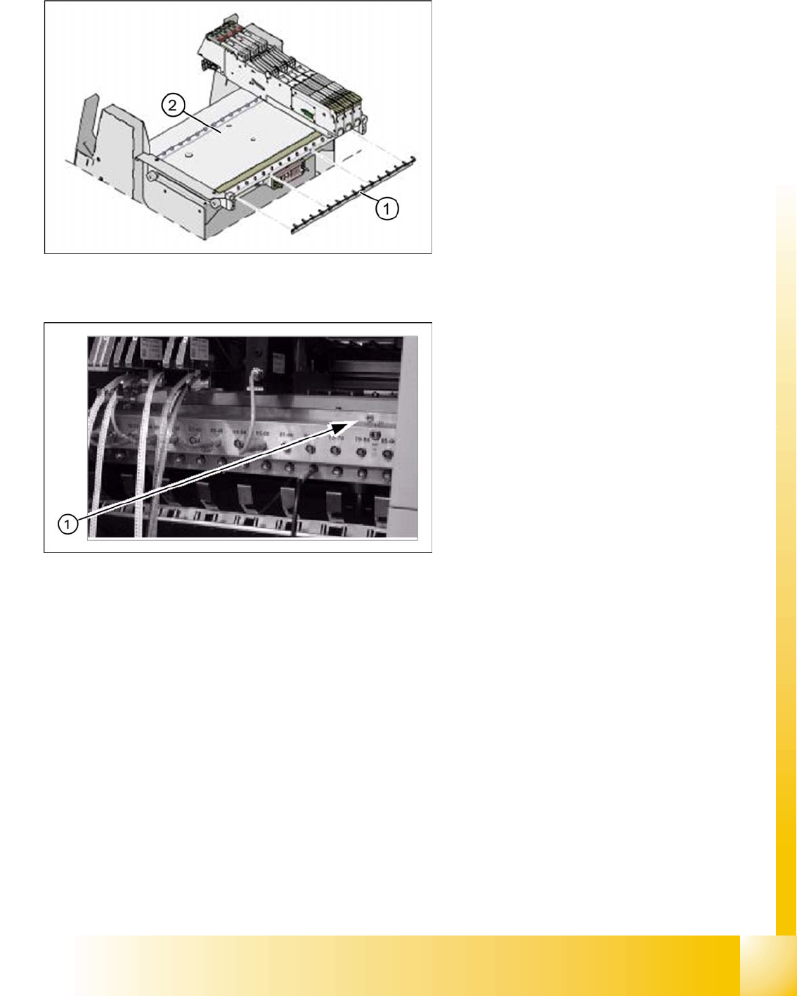
10.2.2.4 Fixtures for S-Feeders
10.2.2.5 Additional Communication unit for splice detection
The Feeder-Fixing is an additional mechanical
safety precaution. It prevents accidential
movement of the feeder on the component table. It
excludes a head crash risk with a wrong
positioned feeder. The feeder-fixation is mounted
on the front side of the component table. The
claws fix the feeder feet. A feeder clamp can be
installed for each of the CO trolleys.
Legend:
1. Feeder fixtures
2. Component table
An additional communication unit for the option
Traceability with splice detection is necessary.
The splice sensors on the communication unit
inform the station software when a new
component lot (reel) is spliced on. This sets the
new fill level for this component automatically.
Legend:
1. The additional communication unit is screwed
into place, together with the CO changeover
table communication unit.