00195193-02 SG D4 FSE en (1).pdf - 第258页
Component handling Optional Extension on the COT Component table Student Guide SIPLACE D4 (FSE) EN 09/2006 Component handling 243 10.2.2.4 Fixtures for S-Feeders 10.2.2.5 Additional Communication unit for splice detectio…
Component handling
Component table Optional Extension on the COT
Student Guide SIPLACE D4 (FSE)
Component handling EN 09/2006
242
10.2.2.2 Compressed Air Supply for Bulkcase Feeders
10.2.2.3 External Power Supply
To keep the time for setup changeovers to a minimum, the CO trolleys can be set up at an external setup
location. The feeder module functions and settings can also be checked there as part of the preparations
for operation. An external power supply unit is available for this purpose. The CO trolley is supplied with
the required operating voltage and compressed air via a supply cable.
Technical data
The unit is supplied with a European standard line cable, a US standard line cable and a connection
cable for linking the voltage supply to the CO trolley.
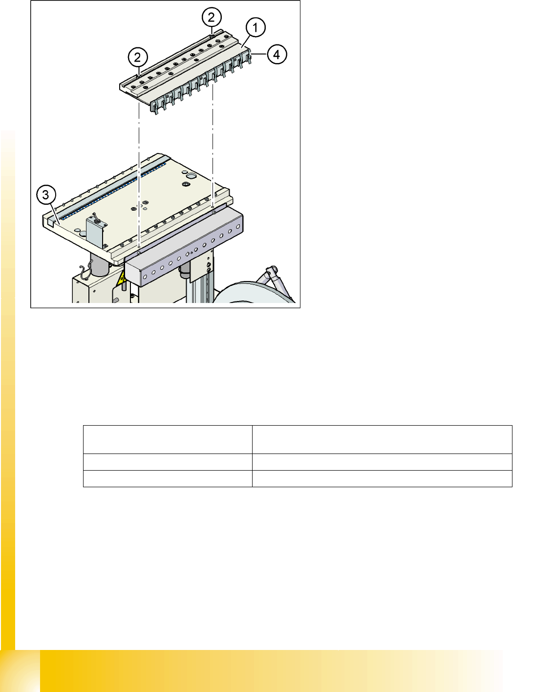
Bulkcase feeders require compressed air. The
optional compressed air supply for bulkcase
feeders is available for this purpose.
Installation is easy. The compressed air distributor
(1) is fixed with two screws (2) to the CO table (3).
The compressed air distributor is then connected
to the CO trolley compressed air supply. At the
back of the compressed air distributor, there is a
row of brackets (4). These fix the bulkcase feeder
modules to the CO table, ensuring optimum
compressed air supply.
Legend:
1. Compressed air distributor
2. 2 x screw DIN 912, M8x20
3. Feeder table plate
4. Brackets
Line voltage 230 V~ ±5 %
120 V~ ±5 %
Compressed air connection max. 1.0 MPa (10 bar)
Output pressure Adjustable via valve
Component handling
Optional Extension on the COT Component table
Student Guide SIPLACE D4 (FSE)
EN 09/2006 Component handling
243
10.2.2.4 Fixtures for S-Feeders
10.2.2.5 Additional Communication unit for splice detection
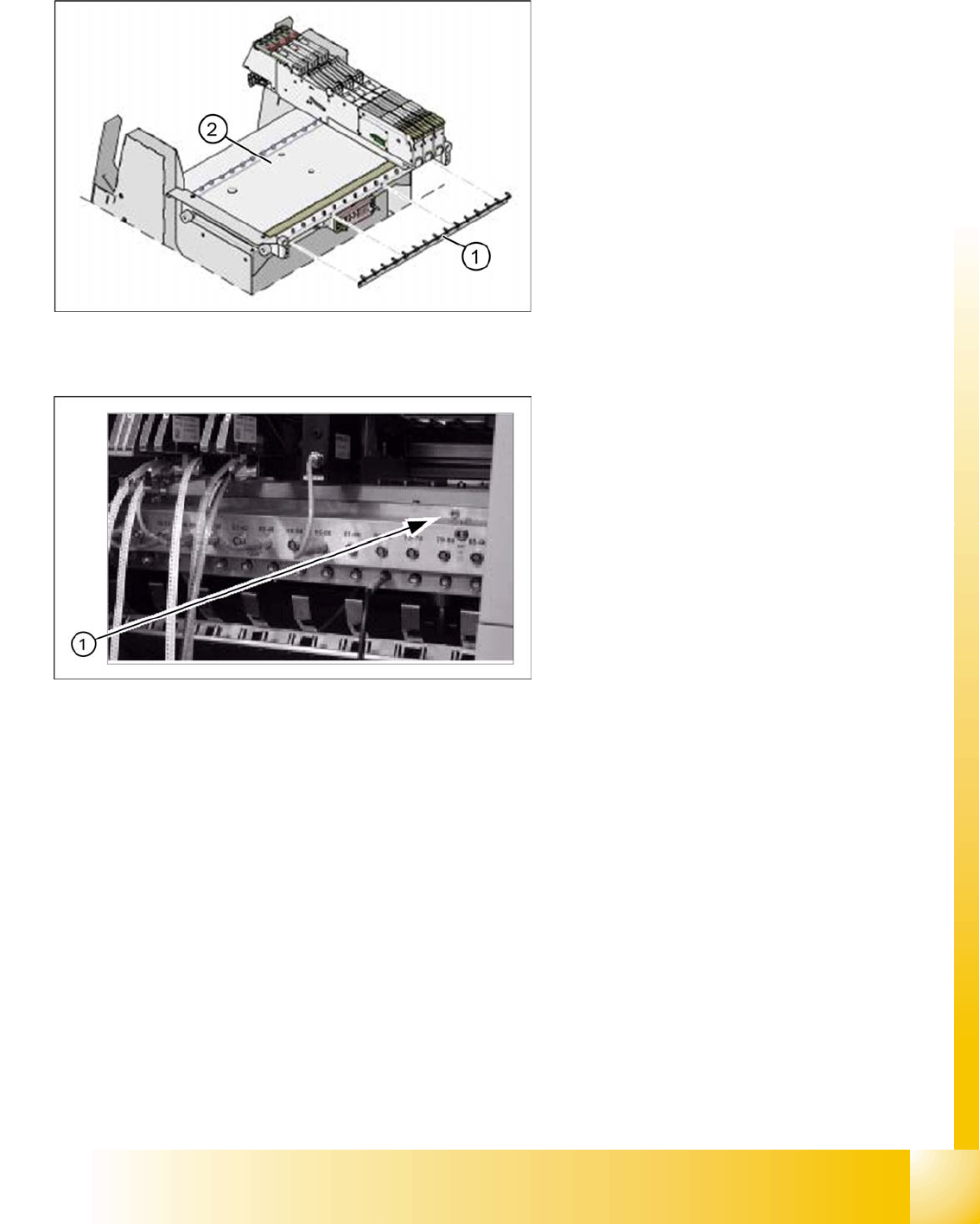
The Feeder-Fixing is an additional mechanical
safety precaution. It prevents accidential
movement of the feeder on the component table. It
excludes a head crash risk with a wrong
positioned feeder. The feeder-fixation is mounted
on the front side of the component table. The
claws fix the feeder feet. A feeder clamp can be
installed for each of the CO trolleys.
Legend:
1. Feeder fixtures
2. Component table
An additional communication unit for the option
Traceability with splice detection is necessary.
The splice sensors on the communication unit
inform the station software when a new
component lot (reel) is spliced on. This sets the
new fill level for this component automatically.
Legend:
1. The additional communication unit is screwed
into place, together with the CO changeover
table communication unit.
Component handling
Pneumatic tape cutter Overview of Pneumatic Cutter with Empty Tape Duct
Student Guide SIPLACE D4 (FSE)
Component handling EN 09/2006
244
10.3 Pneumatic tape cutter
10.3.1 Overview of Pneumatic Cutter with Empty Tape Duct
The pneumatic cutter is fixed to the machine frame with four screws and forms a unit with the empty tape
duct. It separates plastic, aluminum and paper tapes up to a maximum pocket depth of 25 mm. The tape
clippings fall down the waste tape chute, into the waste tape container of the CO trolley.
The empty tape duct is designed to cover the cutting edges of the cutter (risk of injury), to guide the
empty component tapes to the cutter, to integrate the CO reject container and locate the C&P12 nozzle
changer.
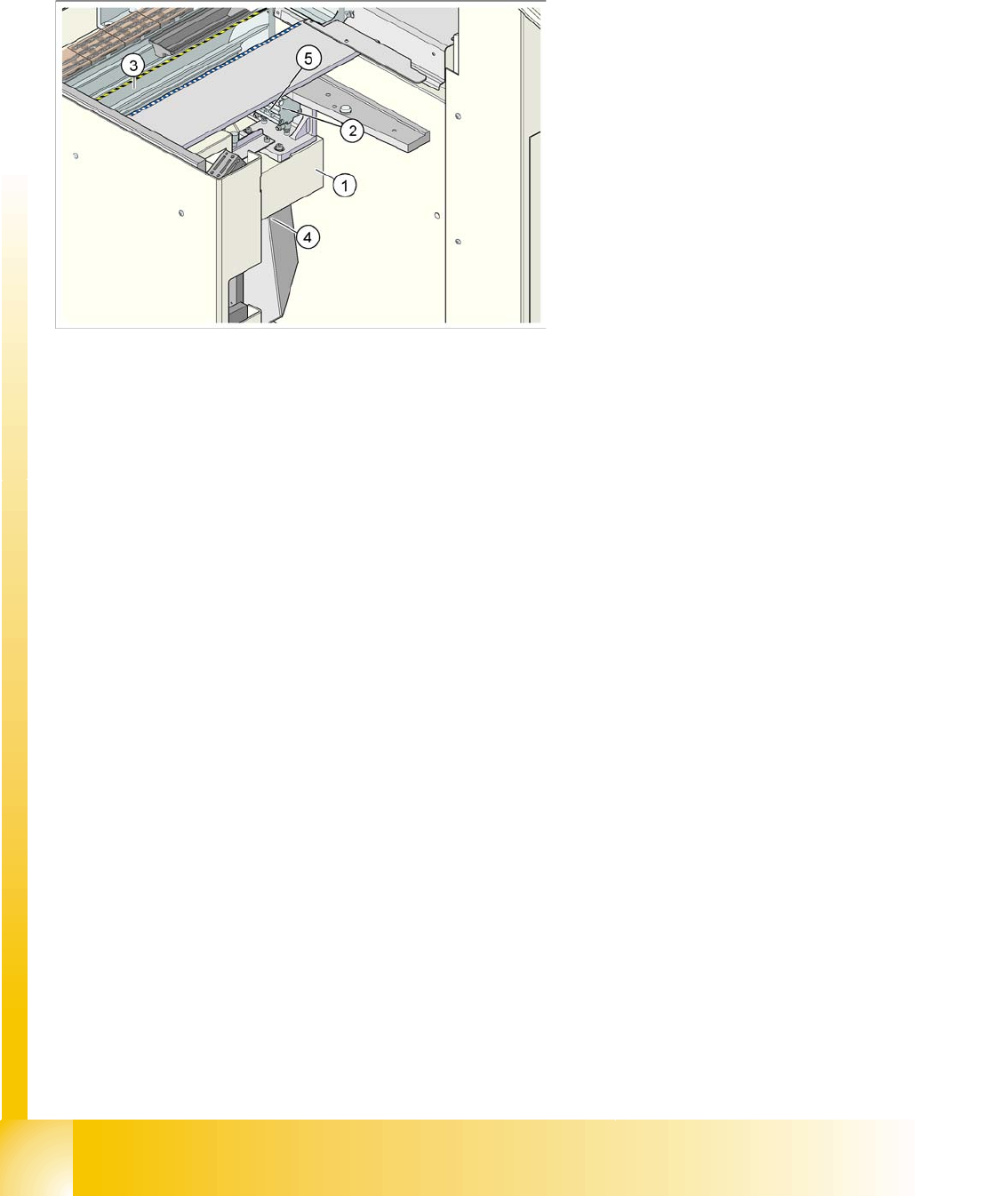
10.3.2 Structure and function of the pneumatic tape cutter
The empty tape duct guides the empty tapes through the opening (3) in the cutter.
The cutter is based on a horizontal frame (1) with a fixed cutting edge and a flexible blade, which is
moved by two short-stroke cylinders (2).At each forwards movement, the device cuts off the tape..
The proximity switch (5) signals the position of the short-stroke cylinder pistons and therefore of the
cutter blade. The control electronics (4) (under the cutter) register, for example, any components in the
tape which have not been cut. Cutting is only performed during the placement procedure. For operational
safety reasons, the tape cutter is integrated into the emergency stop circuit.
Legend:
1. Cross bar
2. Tape cutter
3. Empty tape duct
4. Used tape chute
5. Proximity switch