00195193-02 SG D4 FSE en (1).pdf - 第260页
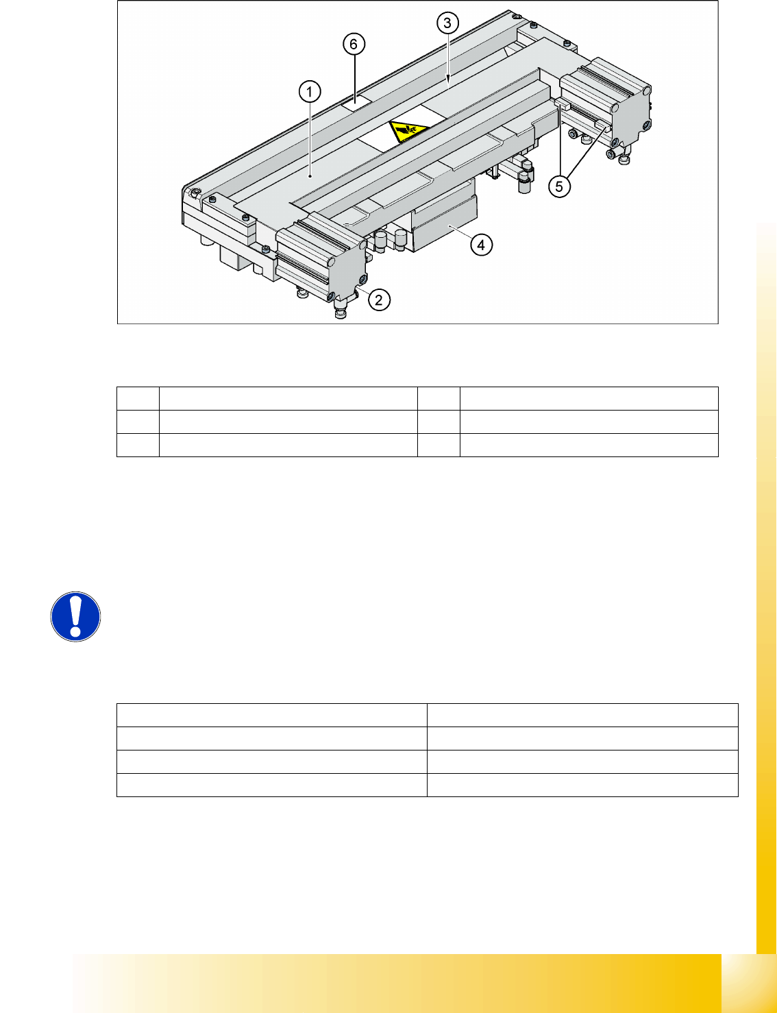
Component handling Structure and function of the pneumatic tape cutte r Pneumatic tape cutter Student Guide SIPLACE D4 (FSE) EN 09/2006 Component handling 245 10.3 - 1: Pneumatic tape cutter Legend The tape cutter is act…

Component handling
Pneumatic tape cutter Overview of Pneumatic Cutter with Empty Tape Duct
Student Guide SIPLACE D4 (FSE)
Component handling EN 09/2006
244
10.3 Pneumatic tape cutter
10.3.1 Overview of Pneumatic Cutter with Empty Tape Duct
The pneumatic cutter is fixed to the machine frame with four screws and forms a unit with the empty tape
duct. It separates plastic, aluminum and paper tapes up to a maximum pocket depth of 25 mm. The tape
clippings fall down the waste tape chute, into the waste tape container of the CO trolley.
The empty tape duct is designed to cover the cutting edges of the cutter (risk of injury), to guide the
empty component tapes to the cutter, to integrate the CO reject container and locate the C&P12 nozzle
changer.
10.3.2 Structure and function of the pneumatic tape cutter
The empty tape duct guides the empty tapes through the opening (3) in the cutter.
The cutter is based on a horizontal frame (1) with a fixed cutting edge and a flexible blade, which is
moved by two short-stroke cylinders (2).At each forwards movement, the device cuts off the tape..
The proximity switch (5) signals the position of the short-stroke cylinder pistons and therefore of the
cutter blade. The control electronics (4) (under the cutter) register, for example, any components in the
tape which have not been cut. Cutting is only performed during the placement procedure. For operational
safety reasons, the tape cutter is integrated into the emergency stop circuit.
Legend:
1. Cross bar
2. Tape cutter
3. Empty tape duct
4. Used tape chute
5. Proximity switch
Component handling
Structure and function of the pneumatic tape cutter Pneumatic tape cutter
Student Guide SIPLACE D4 (FSE)
EN 09/2006 Component handling
245
10.3 - 1: Pneumatic tape cutter
Legend
The tape cutter is activated when the gantry is moving to the placement position. Alternating one of the
cylinders start to front position. Once the first cylinder reaches the front position, the second cylinder is
started. Both signals ’blade in front position’ trigger control unit to withdraw both cylinders at the same
time.
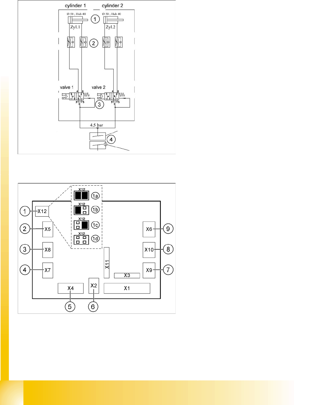
10.3.2.1 Technical data
1 Horizontal frame 4 Electronic control unit
2 Pneumatic cylinder 5 Proximity switch
3 Slot for empty tape 6 Fixed blade
NOTE:
The cutter can be removed within about 15 minutes for service purposes. For
detailed information about dismantling, refer to the service manual.
Compressed air supply 0.5 MPa = 5.0 bar
Compressed air consumption 135 l/min.
Cycle time 1.5 sec per cut
Supply voltages 5 VDC, 24 VDC
Component handling
Pneumatic tape cutter Jumper setting on the control unit at the tape cutter
Student Guide SIPLACE D4 (FSE)
Component handling EN 09/2006
246
10.3.2.2 Pneumatic scheme Tape cutter
10.3.3 Jumper setting on the control unit at the tape cutter
The jumper for the CAN bus addressing must be set according to the corresponding location in the
machine.
Legend:
1. Drive cylinder for cutter blade movement
40 mm stroke
2. Adjustable throttle valve on the pneumatic
cylinder
3. 5/2 way magnetic valve
4. 4.5 bar compressed air supply and 24 V
voltage supply via the PCC safety relay
Cutter only active when protective hoods are
closed
Legend - SIPLACE D4 Jumpers
1. X12 – Jumper for location code of cutter:
1a: Gantry 1
1b: Gantry 2
1c: Gantry 3
1d: Gantry 4
2. X5 – Voltage supply to valve (left)
3. X8 – Proximity switch for stroke cylinder out
(left)
4. X7 – Proximity switch for stroke cylinder in
(left)
5. X4 – CAN bus connection
6. X2 – Voltage supply for cutter +24 V and +5 V
7. X9 – Proximity switch for stroke cylinder in
(left)
8. X10 – Proximity switch for stroke cylinder out
(right)
9. X6 – Voltage supply to valve (right)