00195193-02 SG D4 FSE en (1).pdf - 第289页
Modular conveyor Lifting table functions Conveyor Settings Student Guide SIPLACE D4 (FSE) EN 09/2006 Modular conveyor 273 1 1.3.1 1 Lifting t able functions Lifting table up function Requirements for detectin g that the …
Modular conveyor
Conveyor Settings Control of PCB clamping
Student Guide SIPLACE D4 (FSE)
Modular conveyor EN 09/2006
272
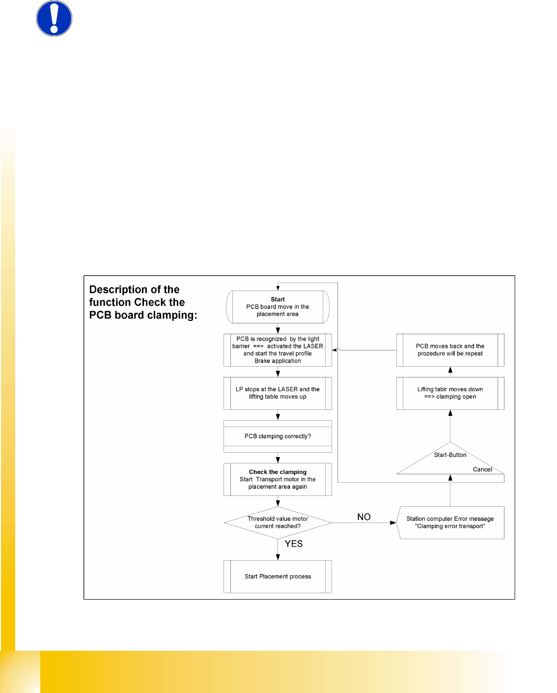
11.3.10 Control of PCB clamping
Function description:
The PCB moves into the placement area, it is recognized by the light barrier, stops at the laser and
the lifting table moves up.
Check PCB clamping: The transport motor in the placement area start again. Is the PCB clamped
correctly the motor current rise up and reach an defined threshold value. Once the board has been
correctly clamped into place, the placement process will begin.
If this threshold is not reached, the system assumes that the board is on its way to the intermediate
or output conveyor and has therefore not been correctly clamped into place.
The station computer will issue the message "PCB not correctly clamped PA1 (PA2)". The process
can be repeated by pressing the "start button".
The lifting table will move downwards, the board will be transported back and the stopper position
will be approached again.
NOTE:
The check whether a PCB is clamping correctly, is controlled with a motor
current check of the transport motor if the PCB board is clamped (Lifting table
up). To check the function you could put a distance plate under the conveyor
side, so that the lifting table can not move to the upper position.
The check is not performed if the option "Vacuum Tooling" is installed.
Modular conveyor
Lifting table functions Conveyor Settings
Student Guide SIPLACE D4 (FSE)
EN 09/2006 Modular conveyor
273
11.3.11 Lifting table functions
Lifting table up function
Requirements for detecting that the lifting table is up:
7-8 increments on the incremental encoder
Check performed by software (see Section 11.4.10 Control of PCB clamping [J 276]).
Dynamic response of approx. 500 ms
Lifting table down function
Requirements for detecting that the lifting table is down:
7-8 increments on the incremental encoder
BERO on the lifting table cylinder
Dynamic response of approx. 480 ms
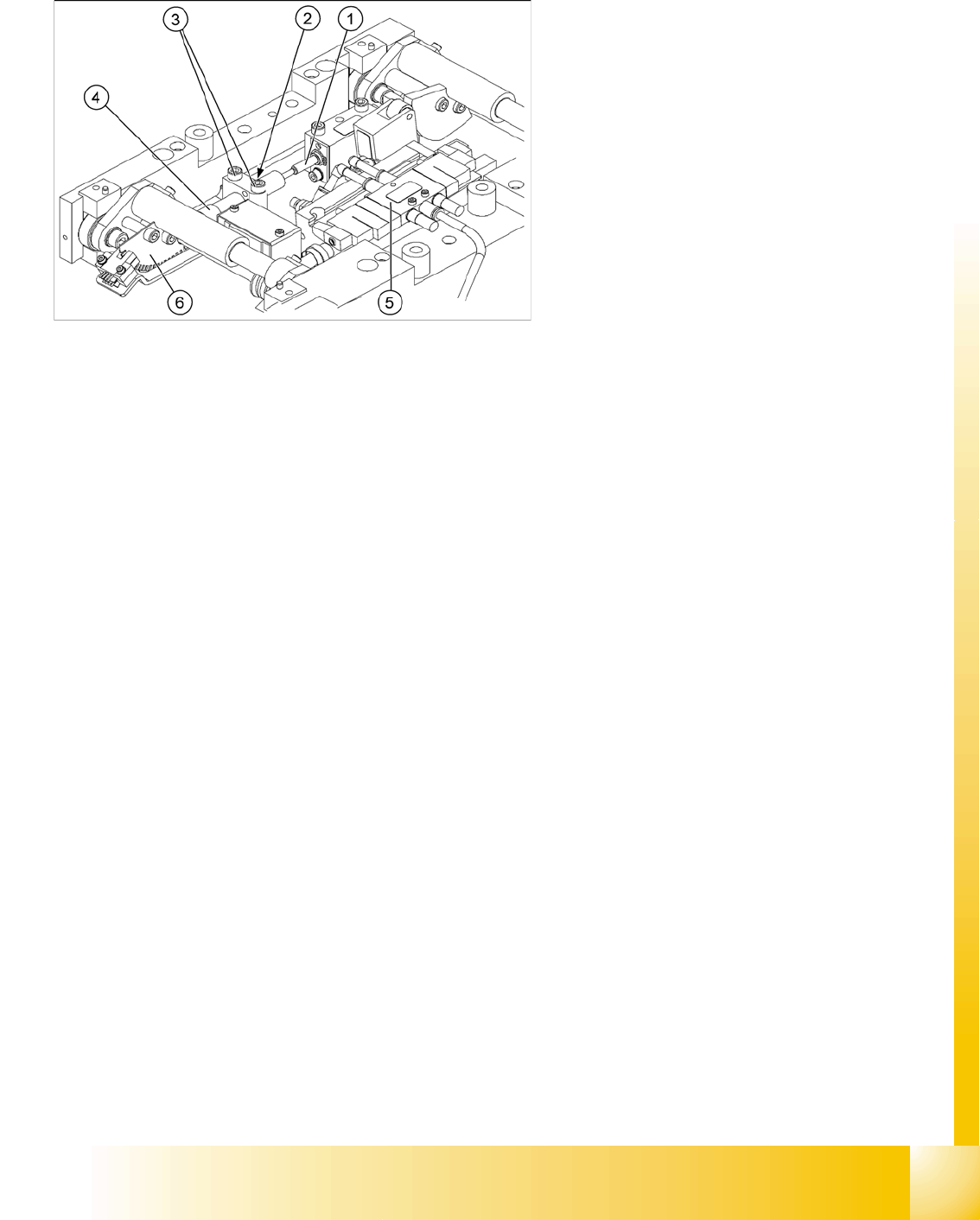
Legend:
1. Actuator
2. Lock nut damper
3. Fastening screws for mounting block
4. Damping unit
5. 3/5 way solenoid valve mounted on lifting table
drive cylinder
6. Fork-type light barriers / incremental disk
Modular conveyor
Conveyor Settings Lifting table functions
Student Guide SIPLACE D4 (FSE)
Modular conveyor EN 09/2006
274
11.3.11.1 Setting the lifting table damping unit
11.3.11.2 Adjusting the Speed of the Lifting Table
The damping unit (1) allows the lifting table to
move gently upwards.When the PCB is clamped,
it also prevents excessive bounce by the PCB.
X Check whether the damping unit (1) is fixed
with the locknut (2) in the mounting block and
that the plunger (3) of the damping unit is just
touching the actuator (4). In this default
setting, the lifting table should move up gently.
X If this is not the case, loosen the locknut at the
mounting block and turn the damping unit
approx. one rotation into the mounting block..
X Start SITEST and move the lifting table up.
X The lifting table must move up gently.
The PCB clamping should not engage audibly
and there should be no PCB clamping error
message.
X Check the speed of the lifting table and correct
where necessary.
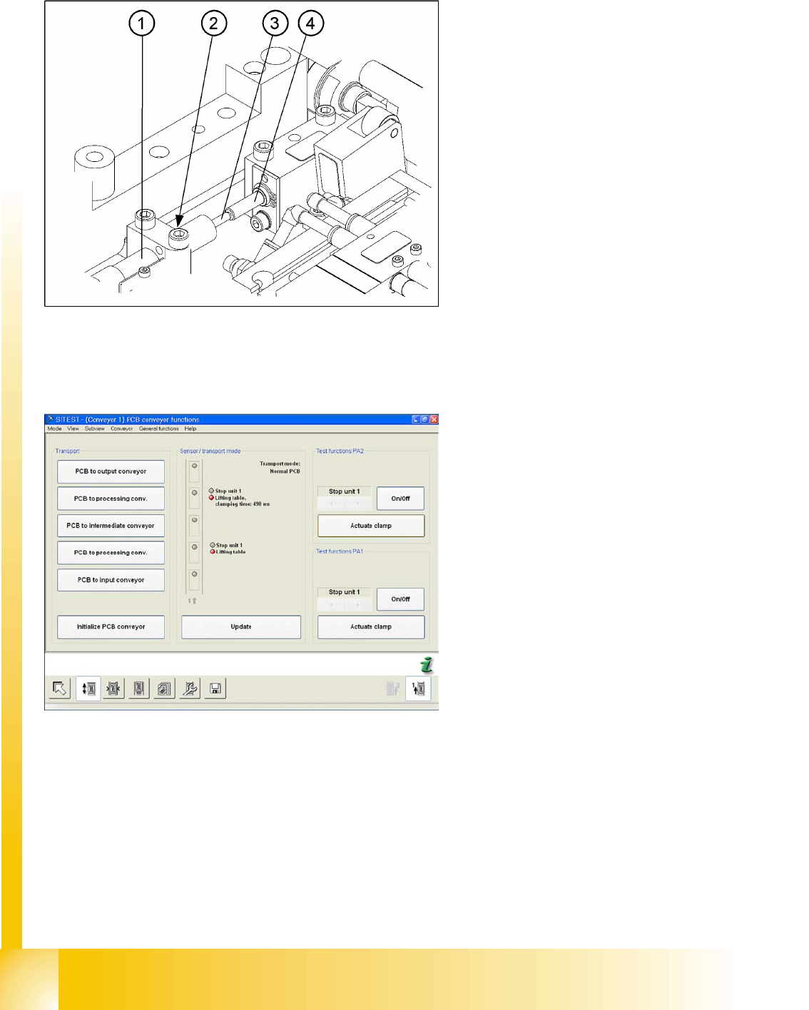
X Switch the machine on and start the SITEST
program.
X In the PCB conveyor functions menu (see
adjacent diagram) you can see the travel time
for the lifting table (from SW 602 upwards).
X Press on the
Actuate clamp
.