00195193-02 SG D4 FSE en (1).pdf - 第295页
Modular conveyor LED display on the TSP 301 conveyor control Conveyor Control Student Guide SIPLACE D4 (FSE) EN 09/2006 Modular conveyor 279 1 1.4.3 LED display on the TSP 301 conveyor control 1 1.4.4 Assignment t able: …
Modular conveyor
Conveyor Control Transport control board TSP 301 with Siemens interface(Option)
Student Guide SIPLACE D4 (FSE)
Modular conveyor EN 09/2006
278
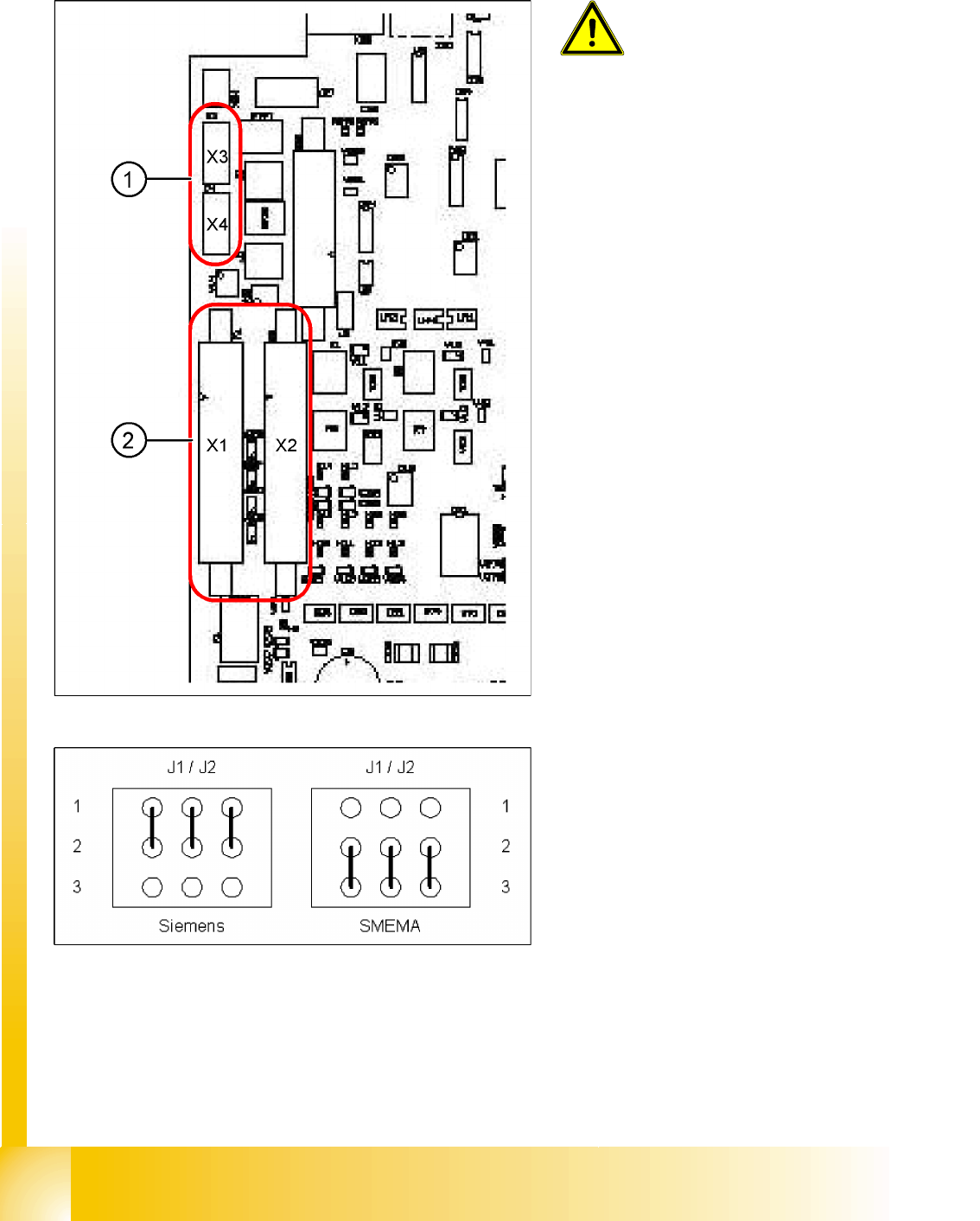
11.4.2 Transport control board TSP 301 with Siemens interface(Option)
WARNING: Destruction of the TSP
board!
The 10 pin Locking clip plug of
SMEMA connections must be
disconnected from the TSP 301!
Application: no modification.
Following modification are necessary for using the
Siemens interface:
X JumperJ1 / J2: need to be moved (see
following diagram).
X Disconnect the connector X3 and X4 on the
TSP 301!
X Connect the Siemens interface cable on the
connector X1 and X2.
Legend:
1. 10-pin plug for SMEMA interface
X3: predecessor station
X4: successor station
2. Connection for Siemens interface
X1: predecessor station
X2: successor station
Modular conveyor
LED display on the TSP 301 conveyor control Conveyor Control
Student Guide SIPLACE D4 (FSE)
EN 09/2006 Modular conveyor
279
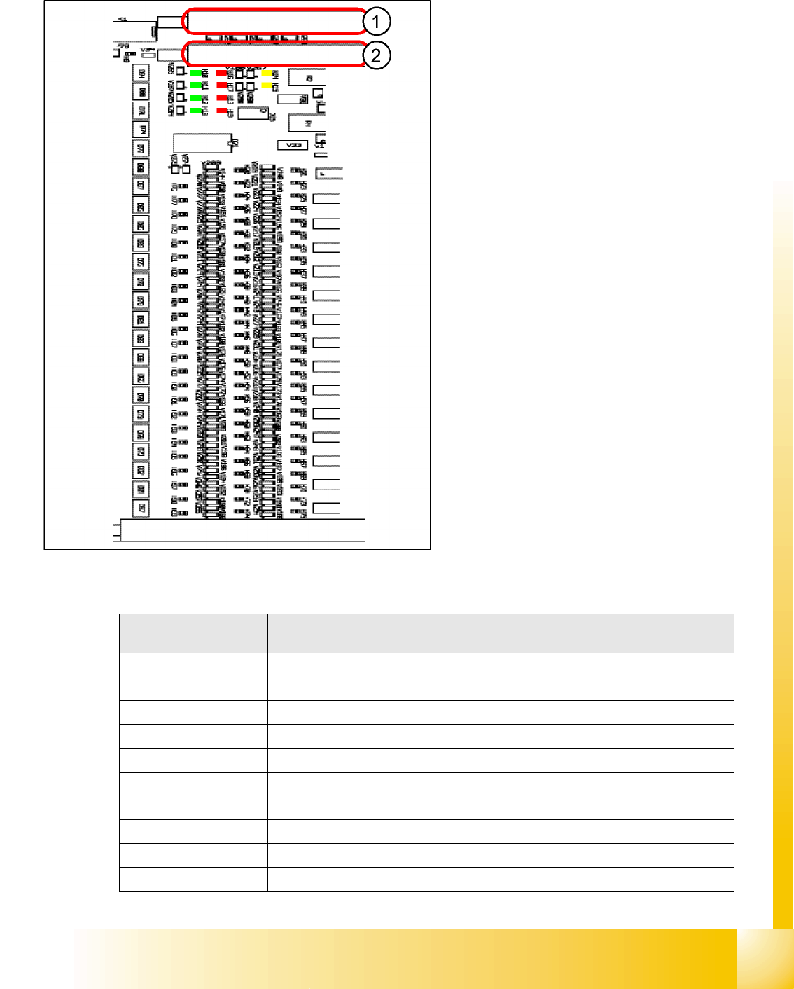
11.4.3 LED display on the TSP 301 conveyor control
11.4.4 Assignment table: LEDs on the TSP 301 conveyor control
Legend:
1. PCB-Handling interface previous station
track1 with diagnosis LED’s PCB-handling
2. PCB-Handling interface following station
track1 with diagnosis LED’s PCB-handling
The "Siemens board handling interface for the
predecessor station of lane 2 with corresponding
LEDs for board handling" plug and the "board
handling interface for the successor station of lane
2 with corresponding LEDs for board handling"
plug are located on the extension board (similar
layout).
Display
/Display
I / O LED assignment
H1 / F1-F5 Fuse F1-F5, Power supply 40 V
H2 / F6 Fuse F6 Power supply 24V
H4(ao) Initializing / control error
H5(ao) CAN bus 1, active
H6(ao) Flashing: Program running
H7(ao) CAN bus 2, active (optional)
H9 Out Interference loop
H14 IN Siemens interface for upstream station
H15 IN Siemens interface for downstream station
H20 IN Lifting table, placement area 1: Fork light barrier A
Modular conveyor
Conveyor Control Assignment table: LEDs on the TSP 301 conveyor control
Student Guide SIPLACE D4 (FSE)
Modular conveyor EN 09/2006
280
H21 IN Lifting table, placement area 1: Fork light barrier B
H22 IN Lifting table, placement area 2: Fork light barrier A
H23 IN Lifting table, placement area 2: Fork light barrier B
H24 IN Laser light barrier, placement area 1: Receiver
H25 IN Laser light barrier, placement area 2: Receiver
H26 IN Not in use
H27 IN Not in use
H28 IN Not in use
H29 IN Not in use
H30 IN Lifting table, placement area 1: Cylinder switch
H31 IN Lifting table, placement area 2: Cylinder switch
H32 IN Right side part: Limit switch
H33 IN Left side part: Limit switch
H34 IN Width adjustment Limit switch, right-hand side
H35 IN Not in use
H36(ao) IN Width driver 1 : Cylinder switch
H37(ao) IN Width driver 2 : Cylinder switch
H38(ao) IN Width driver 1 : Sensor side part
H39(ao) IN Width driver 2 : Sensor side part
H40(ao) IN Width adjustment spindle: right-hand side
H41(ao) IN Width adjustment spindle: Limit switch, left-hand side
H42(ao) IN Not in use
H43(ao) IN Not in use
H44 IN PCB sensor for input conveyor
H45 IN PCB sensor for placement area 1
H46 IN PCB sensor for intermediate conveyor
H47 IN PCB sensor for placement area 2
H48 IN PCB sensor for output conveyor
H49 IN Not in use
H50 IN Not in use
H51 IN Not in use
H52 IN Light scanner "Fluxing", input conveyor
H53 IN Light scanner "Fluxing", placement area 1
H54 IN Light scanner "Fluxing", intermediate conveyor
H55 IN Light scanner "Fluxing", placement area 2
H56 IN Light scanner "Fluxing", output conveyor
H57 IN Not in use
Display
/Display
I / O LED assignment