00195193-02 SG D4 FSE en (1).pdf - 第31页
Operational Safety Warning label W211 on the CEKON plug Safety instructions for moving the component trolley Student Guide SIPLACE D4 (FSE) EN 09/2006 Operational Safety 31 2.2.10 W arning label W2 1 1 on the CEKON plug …
Operational Safety
Warning labels Warning label W209 on the emergency stop buttons
Student Guide SIPLACE D4 (FSE)
Operational Safety EN 09/2006
30
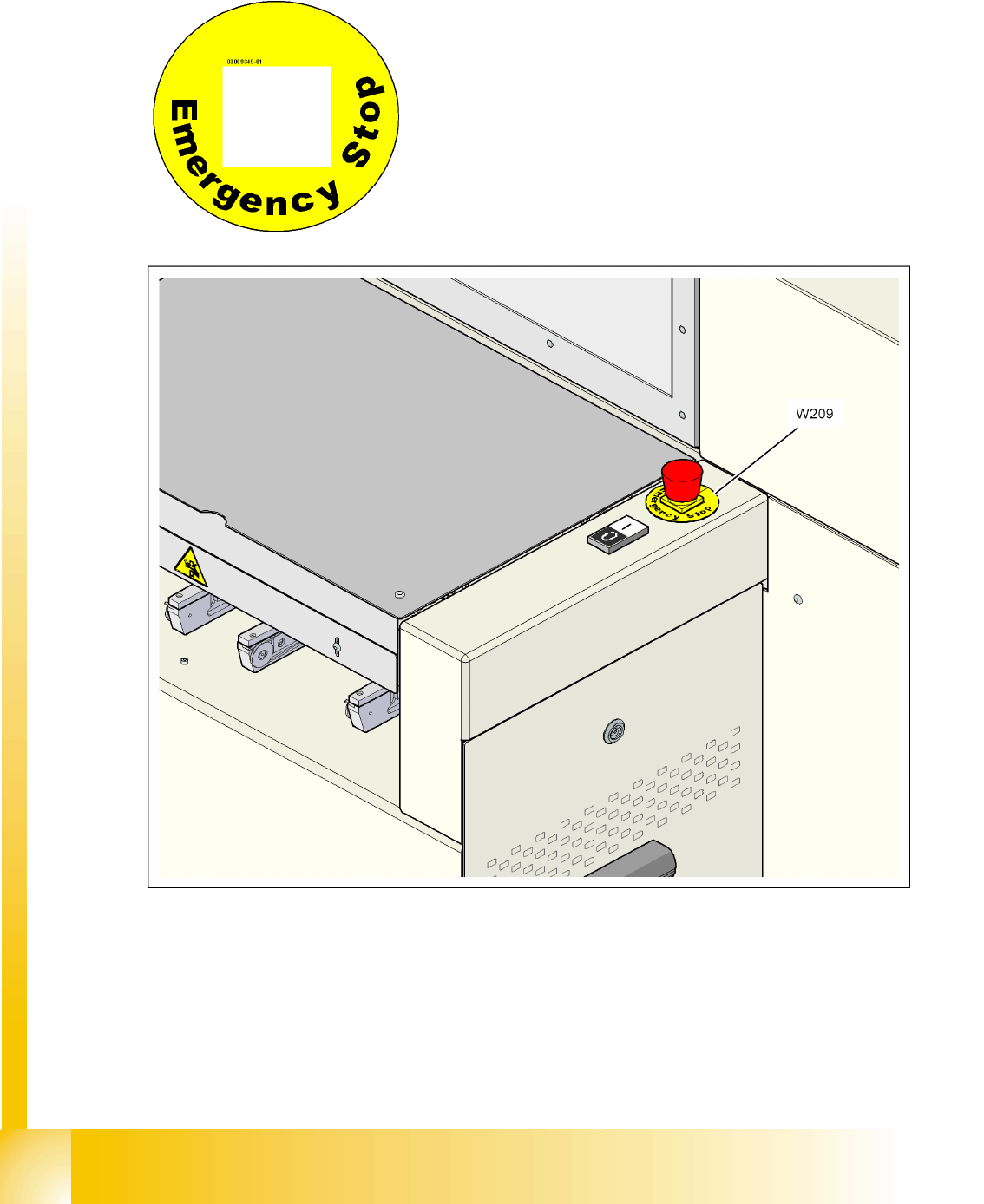
2.2.9 Warning label W209 on the emergency stop buttons
2.2 - 10: Warning label W209 on the emergency stop buttons
W209, article no. 03009349-01
For Australia, Canada, Mexico and USA, warning label W209
is affixed to the extension kit instead of the yellow ring on the
emergency stop buttons.
Article no. 03009349-01 (quantity per machine: 2)
Operational Safety
Warning label W211 on the CEKON plug Safety instructions for moving the component trolley
Student Guide SIPLACE D4 (FSE)
EN 09/2006 Operational Safety
31
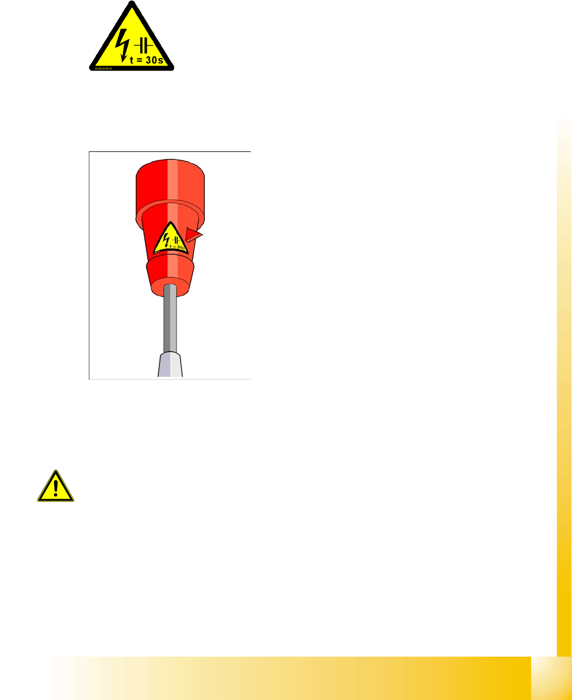
2.2.10 Warning label W211 on the CEKON plug
2.3 Safety instructions for moving the component trolley
X Always hold the handles with both hands when you want to move the component trolley.
X Remember that a component trolley with the full complement of feeder modules can tip over
sideways or forward on gradients of 20 or more.
X Make sure that the surface on which the trolley is moved has a significantly smaller gradient.
X Be careful not to collide with obstacles. The trolley could tip forward if it is traveling fast enough.
RESIDUAL VOLTAGE!
Wait 30 seconds after disconnecting the main power plug from the mains
to allow any residual voltages to dissipate.
NAFTA region: Hazardous Voltage
Residual power at plug prongs and wire ends will cause death or serious
injury. Avoid contact with power plug and/or wire ends for 30 seconds
(quantity per machine: 1)
Article no. 03009351-01
WARNING:
To prevent accidents, ALWAYS follow the rules listed below when you move the
component trolley.
Operational Safety
Safety equipment Switches and buttons on the placement machine
Student Guide SIPLACE D4 (FSE)
Operational Safety EN 09/2006
32
2.4 Safety equipment
2.4.1 Switches and buttons on the placement machine
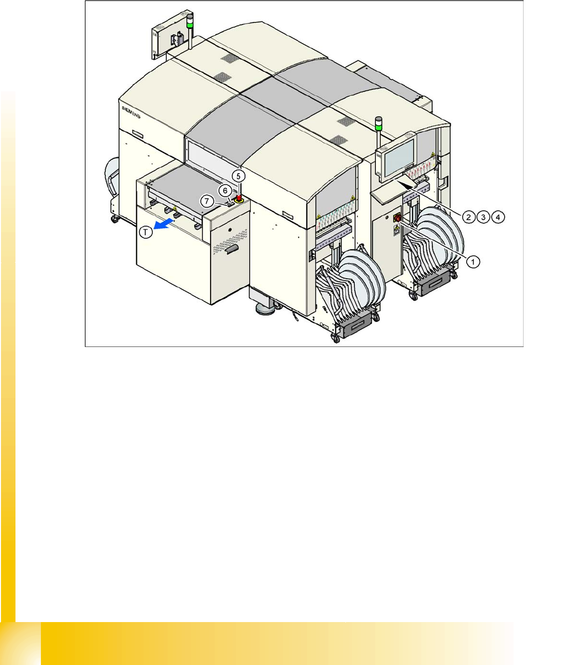
2.4.1.1 Position of switches and buttons on the placement machine
2.4 - 1: Position of switches and buttons - View of the PCB output side
Legend
1. Main switch
2. Stop button (black) on the operator panel on the power supply side
3. Start button (white) on the operator panel on the power supply side
4. Component counter on the operator panel on the power supply side
5. Emergency stop button on the output side
6. Start button (white) on the output side
7. Stop button (white) on the output side
8. PCB transport direction