00195193-02 SG D4 FSE en (1).pdf - 第316页
Sitest Mapping Calibration Student Guide SIPLACE D4 (FSE) EN 09/2006 Sitest 297 12.2.10.1 PCB mapping X Select PCB mapping... 12.2 - 9: Board mapping menu for single conveyors See also: J 12.3.8 PCB mapping [ J 301] 12…
Sitest
Calibration Calibrate the Pick up position
Student Guide SIPLACE D4 (FSE)
Sitest EN 09/2006
296
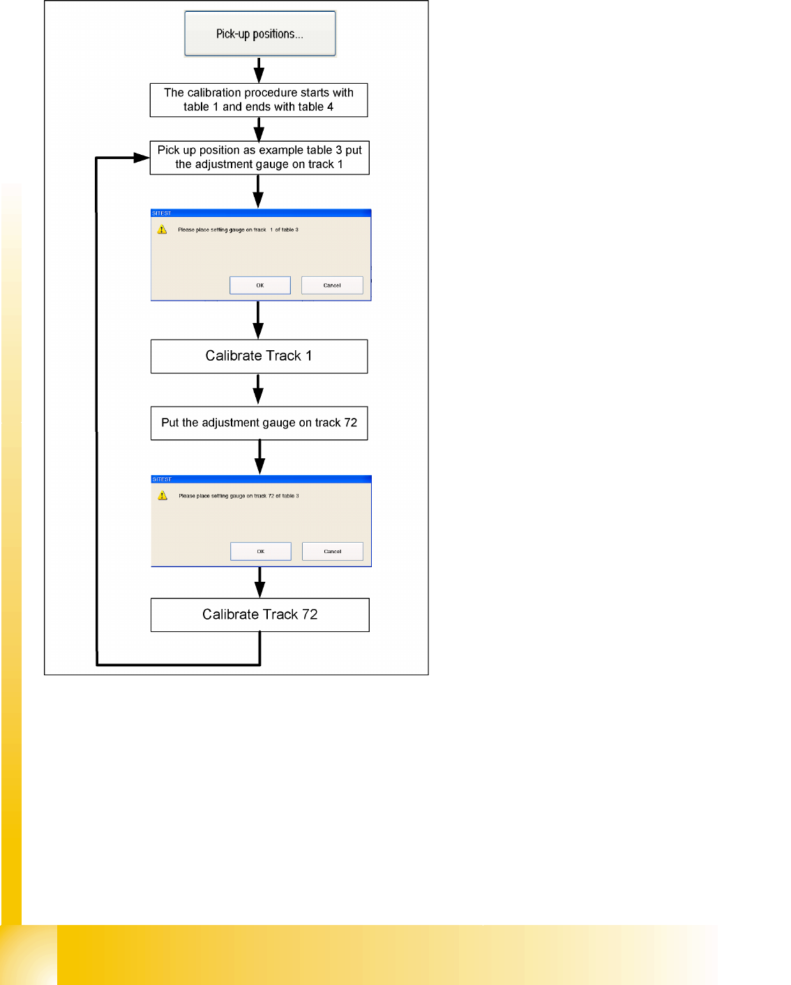
12.2.9 Calibrate the Pick up position
See also:
J 12.3.7.4 Pickup Position (Calibrate the Component Table Track 1- 72) [J 301]
12.2.10 Mapping
in order to measure the machine with the mapping plate, you need version 2 of the mapping plate for
single conveyors and version 4 for dual conveyors. Both versions are used for board and head mapping.
See also:
J 12.3.8 PCB mapping [J 301]
X Select
Pickup positions
The S tales (as in previous machine types) are
manually calibrated with the help of the setting
gauge provided.
Sitest
Mapping Calibration
Student Guide SIPLACE D4 (FSE)
EN 09/2006 Sitest
297
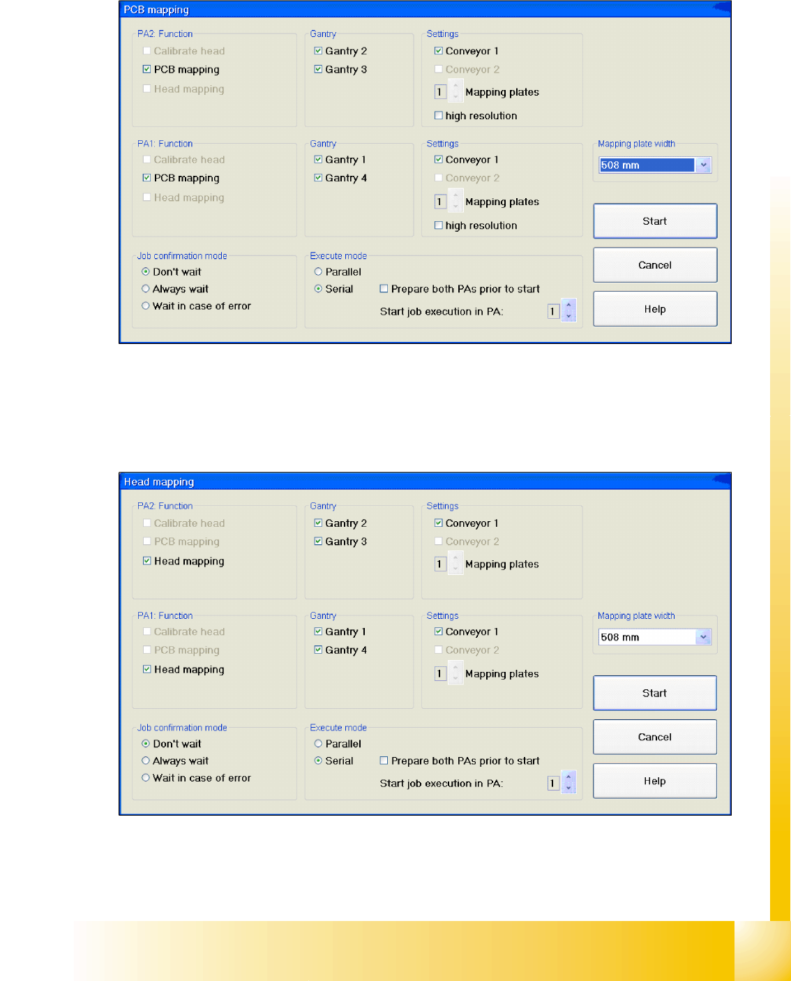
12.2.10.1 PCB mapping
X Select
PCB mapping...
12.2 - 9: Board mapping menu for single conveyors
See also:
J 12.3.8 PCB mapping [J 301]
12.2.10.2 Head mapping
X Select
Head mapping...
12.2 - 10: Head mapping menu for single conveyors
See also:
J 12.3.9 Head Mapping (C&P Head) [J 302]

Sitest
Basic description of all calibration steps Machine zero point:
Student Guide SIPLACE D4 (FSE)
Sitest EN 09/2006
298
12.3 Basic description of all calibration steps
12.3.1 Machine zero point:
The PCB-camera center is the reference at the gantry. All positions at the incremental encoder of X/
Y-axis refer to this camera center.
A drilling is optically centered with the PCB-camera on a defined position at the calibration tool
support.
As soon as the PCB camera for the respective gantry is positioned under the center of this drilling
and the drilling center has been optically centered, the gantry position is set precisely to the following
values:
MA zero point_x_PG1 739500 / MA zero point_y_PG1 662400.
MA zero point_x_PG2 1303500 / MA zero point_y_PG2 1248400
(PG means gantry group)
12.3.2 PCB camera
The pixel size of the CCD sensor is determined (in µm)
It is measured and calculated with Ax/Bx/Cx/Ay/ByCy calibration values. The data is saved at
ca-
mera.xml
in nm (i.e. 1 pixel 11.7x11.7 µm)
The pixel size is:
approx. 11770 nm for the standard PCB camera SST 34,
approx. 11770 nm for the multicolor PCB camera SST 24,
The camera center is determined.
This camera center point is now the reference point for all machine positions!
The Mounting angle of the CCD-chip in the camera to the Ma-coordinate system. This value is saved
as
Position_angle
in the data block of the PCB camera, as
camera.xml
.
12.3.3 Calibration Tool Position
Calibrate the X and Y pick up position of the calibration tool.