00195193-02 SG D4 FSE en (1).pdf - 第318页
Sitest Travel Range Basic description of all calibration steps Student Guide SIPLACE D4 (FSE) EN 09/2006 Sitest 299 12.3.4 T ravel Range 12.3.5 Component camera The Pixel size of the CCD sensors of the camera is determ…

Sitest
Basic description of all calibration steps Machine zero point:
Student Guide SIPLACE D4 (FSE)
Sitest EN 09/2006
298
12.3 Basic description of all calibration steps
12.3.1 Machine zero point:
The PCB-camera center is the reference at the gantry. All positions at the incremental encoder of X/
Y-axis refer to this camera center.
A drilling is optically centered with the PCB-camera on a defined position at the calibration tool
support.
As soon as the PCB camera for the respective gantry is positioned under the center of this drilling
and the drilling center has been optically centered, the gantry position is set precisely to the following
values:
MA zero point_x_PG1 739500 / MA zero point_y_PG1 662400.
MA zero point_x_PG2 1303500 / MA zero point_y_PG2 1248400
(PG means gantry group)
12.3.2 PCB camera
The pixel size of the CCD sensor is determined (in µm)
It is measured and calculated with Ax/Bx/Cx/Ay/ByCy calibration values. The data is saved at
ca-
mera.xml
in nm (i.e. 1 pixel 11.7x11.7 µm)
The pixel size is:
approx. 11770 nm for the standard PCB camera SST 34,
approx. 11770 nm for the multicolor PCB camera SST 24,
The camera center is determined.
This camera center point is now the reference point for all machine positions!
The Mounting angle of the CCD-chip in the camera to the Ma-coordinate system. This value is saved
as
Position_angle
in the data block of the PCB camera, as
camera.xml
.
12.3.3 Calibration Tool Position
Calibrate the X and Y pick up position of the calibration tool.
Sitest
Travel Range Basic description of all calibration steps
Student Guide SIPLACE D4 (FSE)
EN 09/2006 Sitest
299
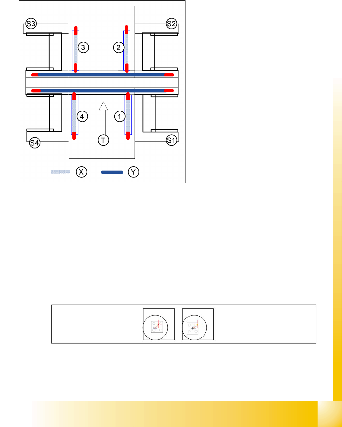
12.3.4 Travel Range
12.3.5 Component camera
The Pixel size of the CCD sensors of the camera is determined in µm. Measured and calculated with
Ax/Bx/Cx/Ay/ByCy calibration values. Saved in
camera.xml
as: XU_Pixel / YU_Pixel in nm
The pixel size is:
approx. 150000 nm for CO camera SST 28 (for 12-segment head)
approx. 81000 nm for CO camera SST 29 (for 6-segment head/12-segment head option)
The camera center is determined.
The Mounting angle of the CCD-chip in the camera to the turning level of the placement star is
measured. The value is saved as Kamera_winkel (camera_angle) in the data block of the CO
camera, in the
camera.xml
.
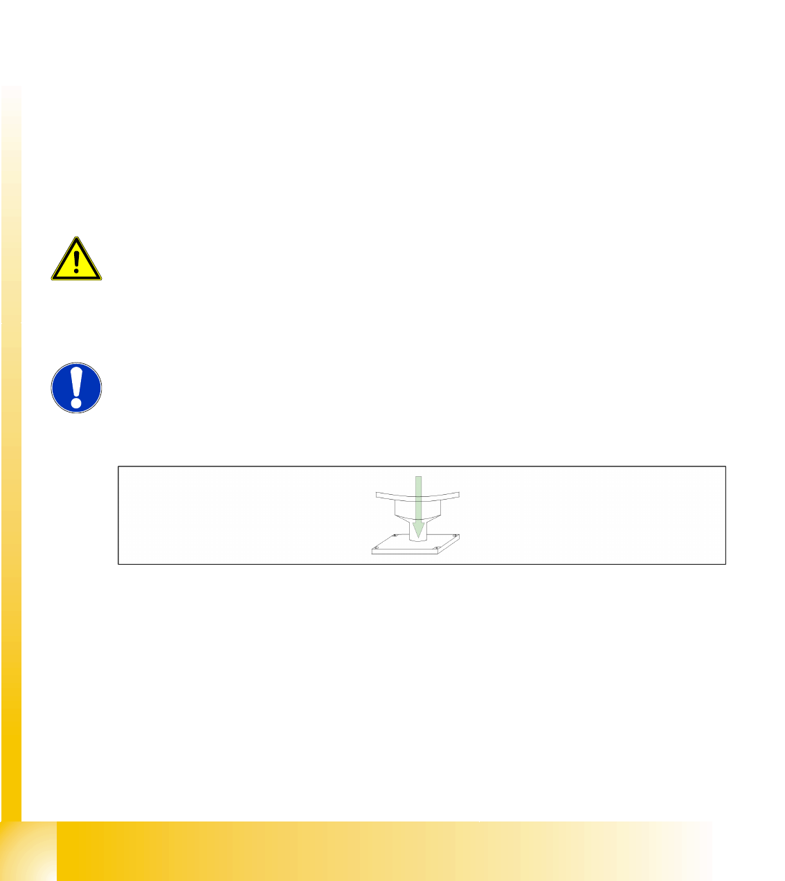
Sequence segment offset top (I):
12.3 - 1: Princple picture of a calibration tool in the camera in 0° (left); in 180°(right).
The gantry moves to the zero pulse, to
calibrate the travel range and then moves on
to the HW limit switch. Measure the position
value at the position counter
The software limit switch (Y +/- 1.5 mm,
X +/- 0.5 mm) is calculated.
In the case of the Y axes, only the outer HW
end position switches are approached in each
case. The other end position of the travel
range is calculated.
Legend:
1 - 4: Gantry 1-4
S1 - S4: Sector 1-4
X: Travel range X
Y: Travel range Y
T: Transport direction
Sitest
Basic description of all calibration steps Component camera
Student Guide SIPLACE D4 (FSE)
Sitest EN 09/2006
300
PCB Camera - CO Camera Offset:
During measurement of the segment offset up (I), the calibration of the PCB camera -> CO camera
offset is performed with segment 1:
The distance in X- and Y- direction of the camera centers is determined in µm.
The top segment offset (I) is compared to a calculated average value. (the segment offset I of
segment 1 is therefore no longer 0.)
Segment 1 is the reference point for calculation of the offset (I and II).
This distance is saved in REAL.MA at ‘Kopfoffsets’ at Kopf 1 Kopfoffset_X /..Y. The segment offset
down (II) for segment 1 is 0 (see below).
The segment offsets for the remaining 11 segments are saved in the PIP_OFF.MA file (as deviation
to segment 1).
Deviation in the X and Y direction of the rotary axis for the remaining segments, compared to
segment 1 (in µm).
Measurement is performed at 0° and 180° or 90° and 270° in each case. The center of the segment
is then determined from these 0/180° or 90/270° values.
The values for the segment offset are saved in the PIP_OFF.MA file.
Sequence segment offset bottom (II):
12.3 - 2: Sequence at one nozzle:
After the segment offset up (I) calibration step has been performed, the calibration procedure for the
segment offset down (II) begins for C&P DLM 3:
Is the calibration tool picked with a Nozzle under 0 degree; optically centered and placed with the
PCB-camera is the exact placement position determined (in µm).
Is the calibration tool picked with a Nozzle under 90 degree; optically centered and placed with the
PCB-camera is the exact placement position determined (in µm).
Is the calibration tool picked with a Nozzle under 180 degree; placed with the PCB-camera is the
exact placement position determined (in µm).
Is the calibration tool picked with a Nozzle under 270 degree; placed with the PCB-camera is the
exact placement position determined (in µm).
ATTENTION:
For the segment offset I (top), the standard deviation value should not exceed
600 µm. The difference between the segments must not exceed +/- 150 µm.
Segment offset II (down) absolute threshold +/- 150 µm and difference in values
max. +/- 150 µm.
NOTE:
The segment offset II (bottom), from the first segment is always 0 that is the
reference value to the other segments.