00195193-02 SG D4 FSE en (1).pdf - 第331页
SIPLACE Measurement tools (D4) SIPLACE AxisTester (SAT) [03002801-xx] Student Guide SIPLACE D4 (FSE) EN 09/2006 SIPLACE Meas urement tools (D4) 31 1 13.1 - 2: Axis tester – bottom view Legend 1. Connection for flat ribb …
SIPLACE Measurement tools (D4)
SIPLACE AxisTester (SAT) [03002801-xx]
Student Guide SIPLACE D4 (FSE)
SIPLACE Measurement tools (D4) EN 09/2006
310
13.1 SIPLACE AxisTester (SAT) [03002801-xx]
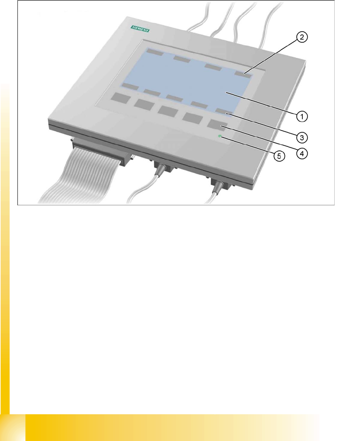
13.1 - 1: Axis tester - Frontview
Legend
1. LCD-Display with 240 x 128 pixels, B/W display, with background illumination
The LCD display shows the menus, and graphics of trigger, track and positioning signals.
– time base
– time measurement values
– signal level and
– cursor positions with corresponding time difference values
will be shown alpha numerically on the graphic display.
2. The assignment of the signals to the BNCs is dynamically shown on the LCD display
3. The assignment of the foil keys is dynamically shown on the LCD display
4. Five membrane keys for menu control
5. Green operating display LED
SIPLACE Measurement tools (D4)
SIPLACE AxisTester (SAT) [03002801-xx]
Student Guide SIPLACE D4 (FSE)
EN 09/2006 SIPLACE Measurement tools (D4)
311
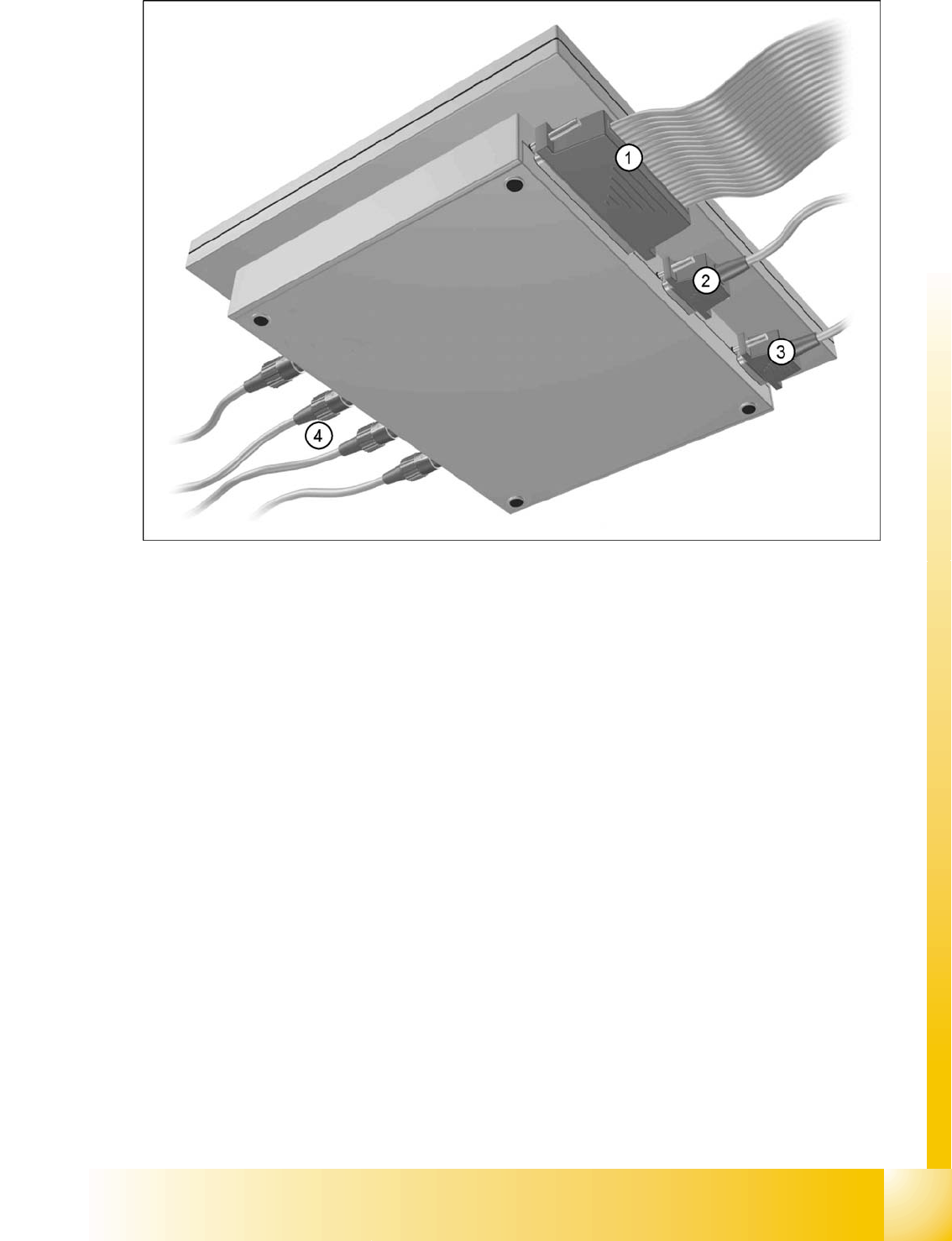
13.1 - 2: Axis tester – bottom view
Legend
1. Connection for flat ribbon cable
– at the SIPLACE axis tester (SAT):
- 37-pin sub-D connector
– at the axis control card
- 37-pin sub-D connector for S-20/23/25/F4/F5 and HS-50 machines with A361 or A362 axis con-
trollers
- 25-pin sub-D connector for S-15/F3, G and wafflepack changer machines with A360 axis
controllers
An adapter is attached to the ribbon cable in order to connect the 25-pin axis controller.
The following operating voltages
+5 V- ±5 % and
±15 V- ±5 %
are supplied from axis controller to SAT via 37 pin flat ribbon cable.
2. 9-pin sub-D connector for the CAN bus cable, e.g. for connecting CAN bus-controlled boards in the
placement machine (transmission speed 128 kBaud to 1 Mbaud, impedance 120 Ohm).
3. 9-pin sub-D connector for the serial interface cable (V24), e.g. for connecting an external PC (max.
transmission speed 188 kBaud).
4. Four BNC, impedance 50ohms. The allocation of the BNC is programmable. The following signals
can be allocated:
– Track signal A or BTTL level, max. 5 V
– Zero pulseTTL level tmin = 1µsec

SIPLACE Measurement tools (D4)
SIPLACE AxisTester (SAT) [03002801-xx] Package
Student Guide SIPLACE D4 (FSE)
SIPLACE Measurement tools (D4) EN 09/2006
312
– End signalTTL level tmin > 10 msec
– TriggerTTL level tmin > 10 msec
– Counting errorTTL level, trigger signal from counting error sensor for the oscilloscope
– Vsetpoint± 10 V, analog signal, Ri = 10 kOhm
– Force± 10 V analog signal, Ri = 10 kOhm
– VREG (total current)± 10 V analog signal, Ri = 10 kOhm
– Position deviation± 10 V analog signal; the signal is generated internally in the axis tester.
13.1.1 Package
The complete SIPLACE axis tester, compl., part no. 03002801-01, is supplied with the following
components:
SIPLACE Axis Tester, part no. 03000761-01
Test cable A361 ... A363 (length 150 cm), with 37-pin plug and 37-pin socket for connecting to the
axis controllers of S2x, F4/F5 and HS placement machines, part no. 03002803-01
CAN bus cable, part no. 00349679-03
RS232 C cable, part no. 3,002,804-1
Manual for axis tester, part no. 00193370-01