00195193-02 SG D4 FSE en (1).pdf - 第36页
Operational Safety Safety equipment Safety and Signaling Circuit S tudent Guide SIPLACE D4 (FSE) Operational Safety EN 09/2006 36 2.4.3 Safety and Signaling Circuit 2.4.3.1 Safety Circuit Function The following condition…
Operational Safety
Position of Pushbutton for Docking and Undocking the Component Trolley Safety equipment
Student Guide SIPLACE D4 (FSE)
EN 09/2006 Operational Safety
35
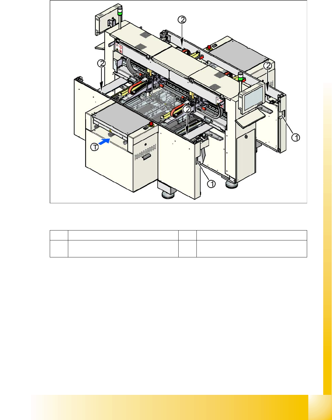
2.4.2 Position of Pushbutton for Docking and Undocking the Component Trolley
2.4 - 3: Position of pushbuttons on the component trolley
Legend
1 Connection for component trolley T PCB transport direction
2 Pushbutton for raising the CO tables, with
feeder cover plate flap above

Operational Safety
Safety equipment Safety and Signaling Circuit
Student Guide SIPLACE D4 (FSE)
Operational Safety EN 09/2006
36
2.4.3 Safety and Signaling Circuit
2.4.3.1 Safety Circuit Function
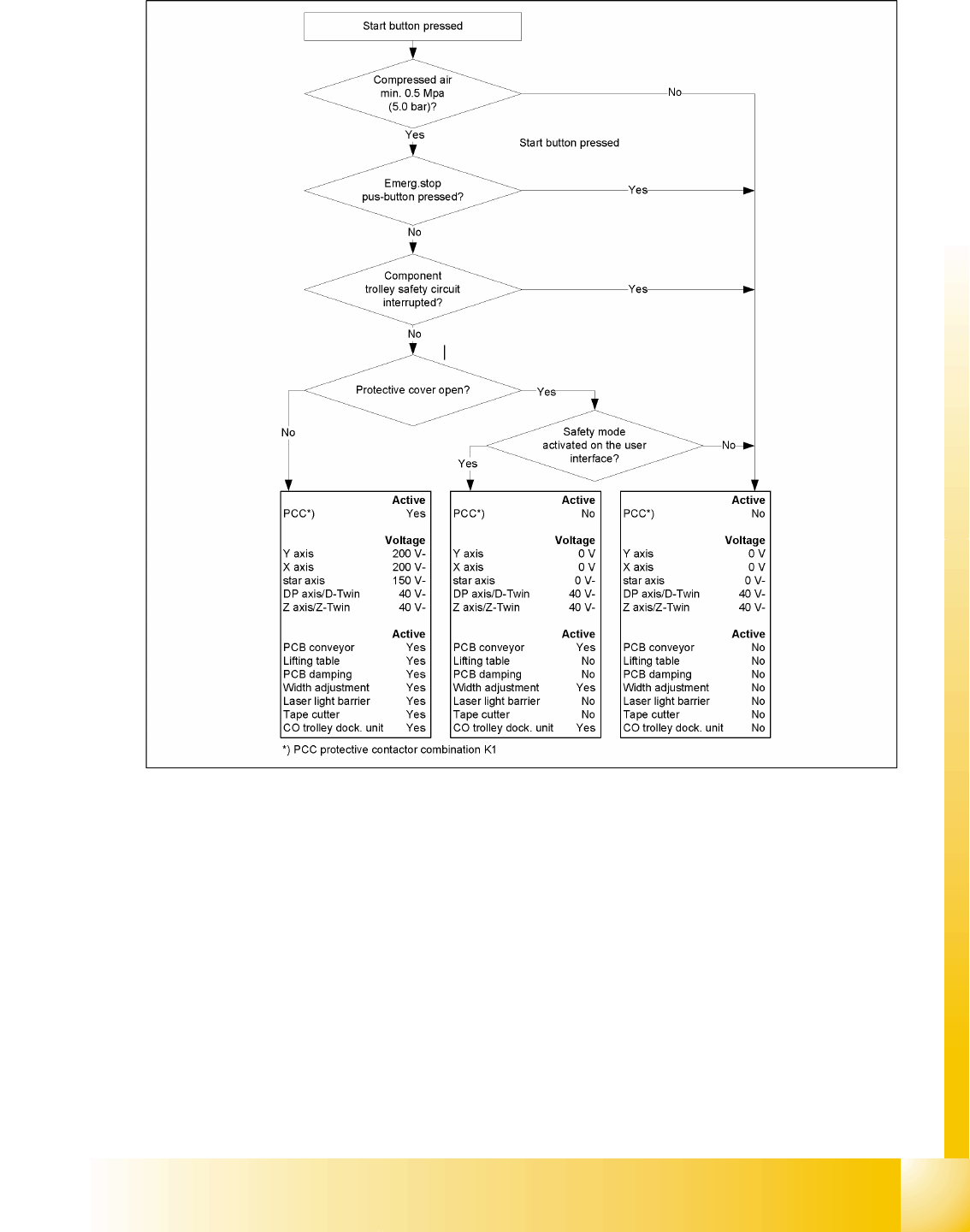
The following conditions must be fulfilled in order to start and operate the placement machine:
All four component trolleys must be docked in and connected.
All protective covers must be closed.
The two cover flaps over the PCB conveyor must be closed.
Both emergency stop buttons must be released.
The cover flaps (option) over the feeder modules must be closed.
The minimum operating pressure must have been reached.
The "software enable" signal must be active. This ensures that the safety circuit is closed.
The power supply must be sending 24 V to the Start buttons and the protective contactor
combination.
If one of the start buttons is pressed now, the protective contactor combination PCC K1 will switch
and enable the following components:
– 200 VDC link voltage for the servo amplifiers for the gantry axes
– 150 VDC link voltage for the star axes
– The axis unit receives a "Servo enable" signal for the servo amplifiers
– 40 VDC operating voltage is switched to the component trolleys.
– 24 VDC operating voltage is switched to the used tape cutters.
– The PCB conveyor control receives the enable signal for the PCB clamping, the PCB stopper
and the lifting table control.
The machine is then ready for use.
Operational Safety
Safety and Signaling Circuit Safety equipment
Student Guide SIPLACE D4 (FSE)
EN 09/2006 Operational Safety
37
2.4.3.2 Safety circuits
2.4 - 4: Safety circuits