00195193-02 SG D4 FSE en (1).pdf - 第39页
Overview General Student Guide SIPLACE D4 (FSE) EN 09/2006 Overview 39 3O v e r v i e w 3.1 General The high-s peed SIPLACE D4 p lacement ma chine co mbines high placement performance with accu racy and flexibility. The …

Operational Safety
ESD guidelines Handling ESD modules
Student Guide SIPLACE D4 (FSE)
Operational Safety EN 09/2006
38
2.5 ESD guidelines
2.5.1 Handling ESD modules
Do not touch electronic modules unless it is absolutely essential to do so in order to carry out other work.
If it is necessary, make sure that you do not touch the pins or printed conductors when you pick up flat
modules.
Do not touch components unless
you are constantly earthed by an ESD wrist strap or
you are wearing ESD shoes or ESD shoe earthing strips on an ESD floor.
Always discharge yourself before you touch an electronic module. To do this, simply touch a conductive
and earthed object immediately before you touch the module (such as unpainted parts of a switch
cabinet, a water pipe, etc.).
Do not allow modules with chargeable and highly insulating materials to touch one another, e.g. plastic
films, insulating table surfaces or items of clothing made from synthetic fibers.
Always place the modules on a conductive surface (table with an ESD coating, conductive ESD foam,
ESD bag or container).
Do not bring modules near visual display units, monitors or televisions. Keep them at least 10 cm away
from the screen.
2.5.2 Measurements and modifications to ESD modules
Measurements of the assemblies may only be taken if
The measuring device has been grounded (e.g. via protective conductor) or
The measuring head of the potential-free measuring device has been briefly discharged before
measurement (e.g. touching blank metal control unit housing).
X Always use an earthed soldering iron if you carry out any soldering work.
2.5.3 Dispatching ESD modules
X Always store modules and components in conductive packaging (e.g. metallized plastic bags or
metal sleeves) and dispatch them in conductive packaging.
If the packaging is not conductive, place the modules in a conductive envelope before packaging. Use
conductive expanded rubber, ESD bags, domestic aluminum foil or paper, for example. NEVER use
plastic bags or film.
X If the module has integral batteries, ensure that the conductive packaging does not touch or short-
circuit the battery terminals and, if necessary, first cover the terminals with insulating tape or
material.
Overview
General
Student Guide SIPLACE D4 (FSE)
EN 09/2006 Overview
39
3Overview
3.1 General
The high-speed SIPLACE D4 placement machine combines high placement performance with accuracy
and flexibility. The machines use the Collect&Place placement method.
The SIPLACE D4 placement machine is equipped with four gantries, for fast and accurate positioning
along the X and Y axes.
Each gantry has a 12-segment C&P head (C&P12). Each placement area is served by two gantries:
Placement area 1 Gantries 1 and 4
Placement area 2 Gantries 2 and 3
The components are optically centered with the help of a digital Vision module. Two different CO
cameras are available for the placement heads: a standard camera and a high-resolution CO camera.
A five-segment PCB conveyor, consisting of input conveyor, processing conveyor 1, intermediate
conveyor, processing conveyor 2 and output conveyor, transports the components to the processing
positions. PCB transport can be performed with a single or flexible dual conveyor (with stationary side
either on the left or right). A PCB camera is used to optically center the boards.
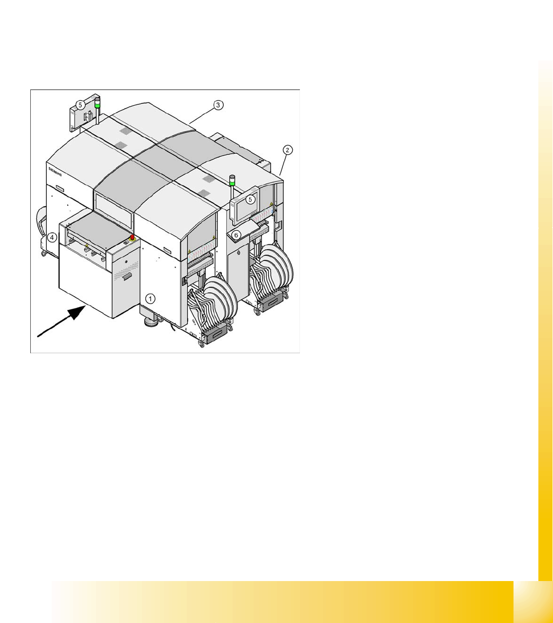
Legend:
1. Sector 1
2. Sector 2
3. Sector 3
4. Sector 4
5. Monitor (on both sides)
6. Keyboard (on both sides)

Overview
General Specification SIPLACE D4
Student Guide SIPLACE D4 (FSE)
Overview EN 09/2006
40
3.1.1 Specification SIPLACE D4
Types of placement head 12-segment Collect&Place head (C&P12)
Number of gantries 4
Placement rate
(Benchmark test)
60,000 comp./h
Placement positions 3,500 / gantry
Range of components
0.6 x 0.3 mm
2
(0201) to 18.7 x 18.7 mm
2
Max. component height 6 mm
Placement accuracy / angle accuracy Camera type 28: ± 60 µm, ± 0.5° (3 s), ± 80 µm, ± 0.7° (4 s)
Camera type 29: ± 60 µm, ± 0.5° (3 s), ± 80 µm, ± 0.7° (4 s)
Component feeding 4 CO trolleys with tape reel holder and integrated waste containers
(12 locations à 30 mm width per CO trolley)
Feeder module types Tape, bulkcase, stick magazines, application-specific OEM feeder
modules, surftape feeder modules (8, 12, 16 mm), waffle pack trays
Feeding capacity 48 tape feeder modules 3 x 8 mm S (144 tracks)
48 tape feeder modules 2 x 8 mm S (96 tracks)
48 tape feeder modules x 12/16 mm S (48 tracks)
32 tape feeder modules x 24/32 mm S (32 tracks)
PCB format
(LxW)
Single conveyor
50 x 50 mm
2
to 368 x 460 mm
2
50 x 110 mm
2
to 610 x 460 mm
2
(option "Long board")
Width up to 508 mm on request
Dual conveyor
50 x 50 mm
2
to 368 x 216 mm
2
50 x 110 mm
2
to 610 x 216 mm
2
(option "Long board")
Width up to 242 mm on request
Dual conveyor in Single conveyor mode
50 x 50 mm
2
to 368 x 380 mm
2
50 x 110 mm
2
to 610 x 380 mm
2
(option "Long board")
Width up to 430 mm on request
PCB thickness 0.3 to 4.5 mm (thicker PCBs available on request)