00195193-02 SG D4 FSE en (1).pdf - 第40页
Overview General Specification SIPLACE D4 S tudent Guide SIPLACE D4 (FSE) Overview EN 09/2006 40 3.1.1 Specification SIPLACE D4 Types of placement head 12-segm ent Collect & Place hea d (C&P12) Number of ga ntrie…
Overview
General
Student Guide SIPLACE D4 (FSE)
EN 09/2006 Overview
39
3Overview
3.1 General
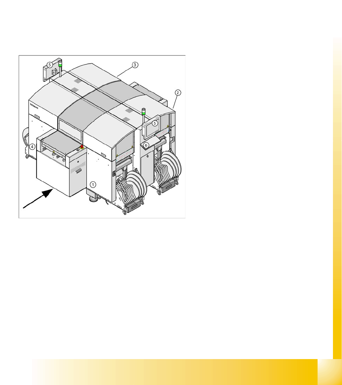
The high-speed SIPLACE D4 placement machine combines high placement performance with accuracy
and flexibility. The machines use the Collect&Place placement method.
The SIPLACE D4 placement machine is equipped with four gantries, for fast and accurate positioning
along the X and Y axes.
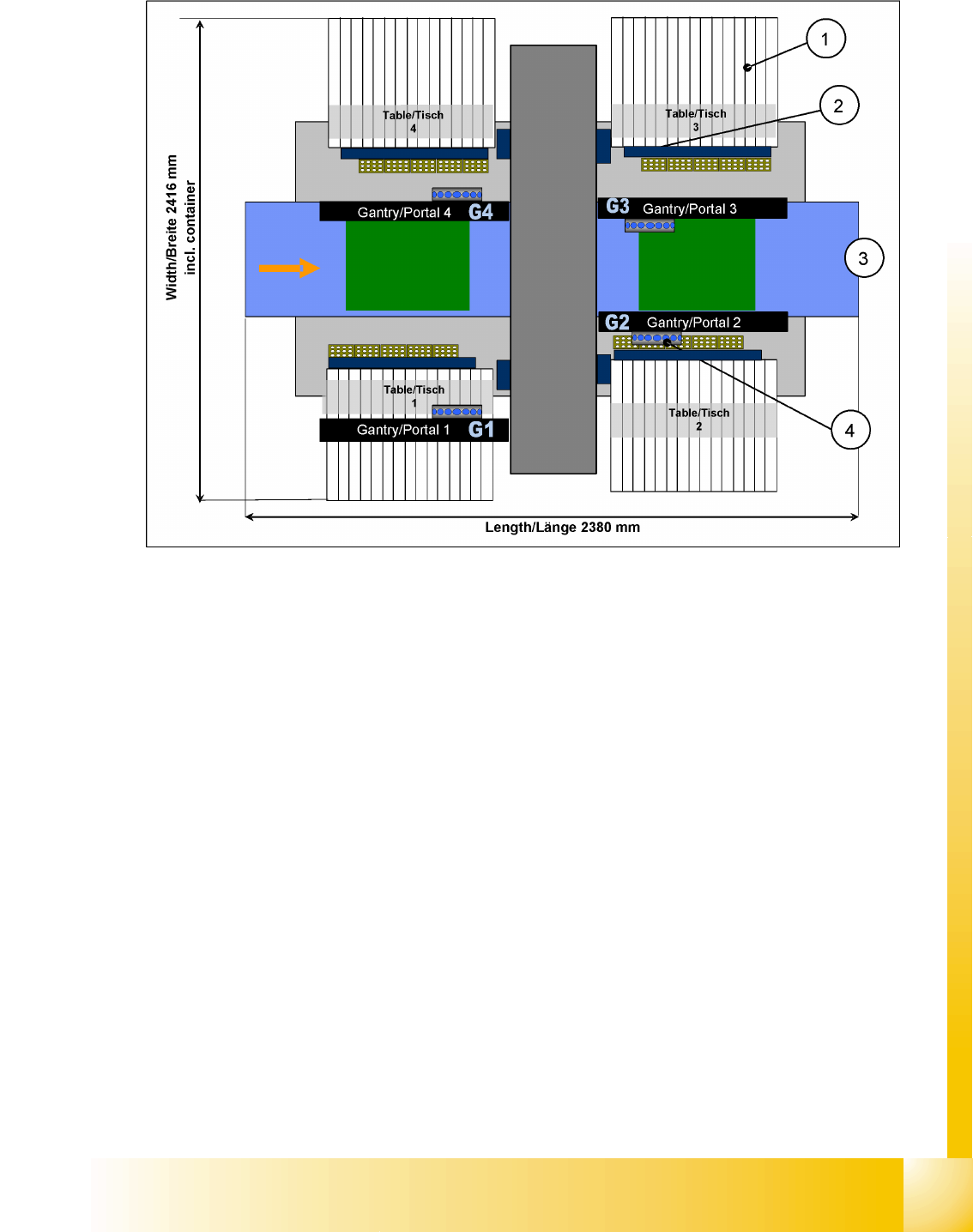
Each gantry has a 12-segment C&P head (C&P12). Each placement area is served by two gantries:
Placement area 1 Gantries 1 and 4
Placement area 2 Gantries 2 and 3
The components are optically centered with the help of a digital Vision module. Two different CO
cameras are available for the placement heads: a standard camera and a high-resolution CO camera.
A five-segment PCB conveyor, consisting of input conveyor, processing conveyor 1, intermediate
conveyor, processing conveyor 2 and output conveyor, transports the components to the processing
positions. PCB transport can be performed with a single or flexible dual conveyor (with stationary side
either on the left or right). A PCB camera is used to optically center the boards.
Legend:
1. Sector 1
2. Sector 2
3. Sector 3
4. Sector 4
5. Monitor (on both sides)
6. Keyboard (on both sides)

Overview
General Specification SIPLACE D4
Student Guide SIPLACE D4 (FSE)
Overview EN 09/2006
40
3.1.1 Specification SIPLACE D4
Types of placement head 12-segment Collect&Place head (C&P12)
Number of gantries 4
Placement rate
(Benchmark test)
60,000 comp./h
Placement positions 3,500 / gantry
Range of components
0.6 x 0.3 mm
2
(0201) to 18.7 x 18.7 mm
2
Max. component height 6 mm
Placement accuracy / angle accuracy Camera type 28: ± 60 µm, ± 0.5° (3 s), ± 80 µm, ± 0.7° (4 s)
Camera type 29: ± 60 µm, ± 0.5° (3 s), ± 80 µm, ± 0.7° (4 s)
Component feeding 4 CO trolleys with tape reel holder and integrated waste containers
(12 locations à 30 mm width per CO trolley)
Feeder module types Tape, bulkcase, stick magazines, application-specific OEM feeder
modules, surftape feeder modules (8, 12, 16 mm), waffle pack trays
Feeding capacity 48 tape feeder modules 3 x 8 mm S (144 tracks)
48 tape feeder modules 2 x 8 mm S (96 tracks)
48 tape feeder modules x 12/16 mm S (48 tracks)
32 tape feeder modules x 24/32 mm S (32 tracks)
PCB format
(LxW)
Single conveyor
50 x 50 mm
2
to 368 x 460 mm
2
50 x 110 mm
2
to 610 x 460 mm
2
(option "Long board")
Width up to 508 mm on request
Dual conveyor
50 x 50 mm
2
to 368 x 216 mm
2
50 x 110 mm
2
to 610 x 216 mm
2
(option "Long board")
Width up to 242 mm on request
Dual conveyor in Single conveyor mode
50 x 50 mm
2
to 368 x 380 mm
2
50 x 110 mm
2
to 610 x 380 mm
2
(option "Long board")
Width up to 430 mm on request
PCB thickness 0.3 to 4.5 mm (thicker PCBs available on request)
Overview
Configuration SIPLACE D4 General
Student Guide SIPLACE D4 (FSE)
EN 09/2006 Overview
41
3.1.2 Configuration SIPLACE D4
3.1 - 1: SIPLACE D4 configuration
Legend
1. S-table with S-feeder
2. Reject container for components and nozzles, without sensor for the reject container
3. Single/dual conveyor with stationary side on left or right
4. 4x C&P12