00195193-02 SG D4 FSE en (1).pdf - 第50页
Overview General Overview of Assemblies Power Supply Unit S tudent Guide SIPLACE D4 (FSE) Overview EN 09/2006 50 Legend: 1. F1 : 3x 230 V AC SZ1 : main contactor MS1 : Motor protection switch S1 : main switch 2. F2 : 220…
Overview
Power Supply Unit General Overview of Assemblies
Student Guide SIPLACE D4 (FSE)
EN 09/2006 Overview
49
3.2.4 Power Supply Unit
The main power supply unit is mounted on a compact rack unit and is located on the left of the middle
section of the machine. From outside, you can only see the red main switch.
A lockable door prevents access to the power supply.
3.2.4.1 Overview of Voltages in the Power Supply Unit
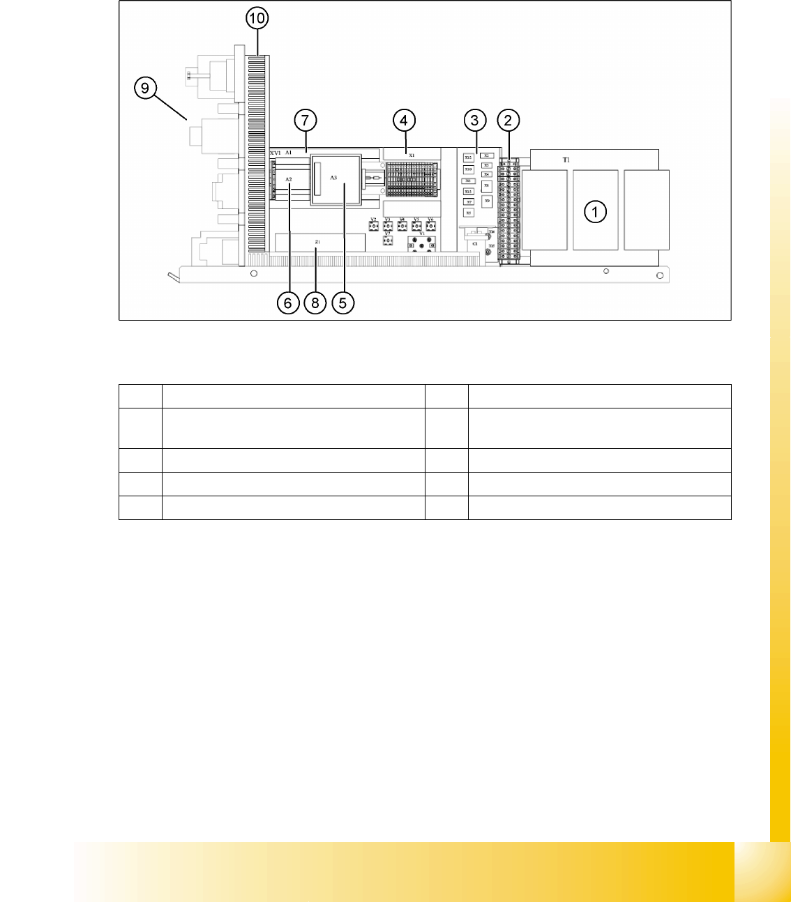
3.2 - 5: Power supply – view of right-hand side
Legend
1 Transformer 1 6 Power supply A2 (5 V/6.3 A)
2 Secondary terminal strip with fuses (output
voltage T1)
7 Power supply A1 (24 V/40 A)
3 Connector strip X2-X10, X12, X13 8 Line filter Z1 (input voltage)
4 Terminal strip X1 9 Front view (see following diagram)
5 Power fail board A3 10 Inrush current limiter (behind the cable duct)
Overview
General Overview of Assemblies Power Supply Unit
Student Guide SIPLACE D4 (FSE)
Overview EN 09/2006
50
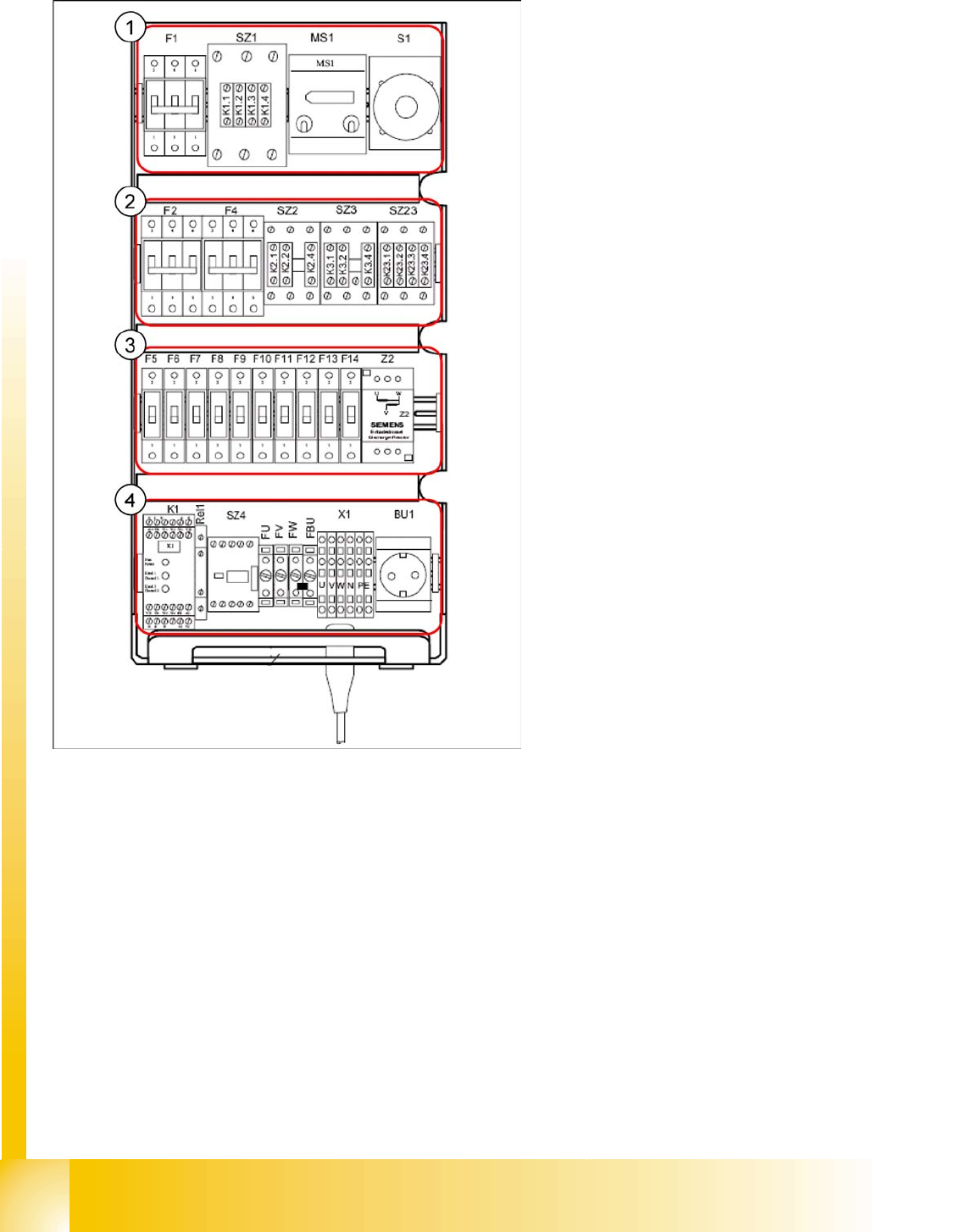
Legend:
1. F1: 3x 230 V AC
SZ1: main contactor
MS1: Motor protection switch
S1: main switch
2. F2: 220 V AC for 5 V power supply
F4: 3x 140 VAC X/Y axes
SZ2,SZ3, SZ23: auxiliary contactors U,V,W for
X/Y servos
3. F5: 150 V DC star axis servo
F6: 40 V DC Z/DP axis servo
F7: 40 V DC CO table
F8: 40 V DC PCB handling (conveyor)
F9: 8 V DC CO table
F10: 48 V DC Vision illumination
F11: 24 V DC terminal strip distributor 2/4
F12: 24 V DC Microbox PC (MC)/control "ON"
(K1)
F13: 24 V DC Box PC (SR)/axis unit 1/2
F14: 24 V DC conveyor control (CC 301)/
monitors
Z2: discharge inductor
4. K1: protective contactor combination
Relay1: control ON - button
SZ4: control ON - software
FU: fuse 6.3 AT 220 VAC to GND
FV: fuse 6.3 AT 220 VAC to GND
FW: fuse 6.3 AT 220 VAC to GND
FBU: fuse 6.3 AT 220 VAC to GND
X1: feed in - terminal strip
BU1: service socket
Overview
Changeover Table Components General Overview of Assemblies
Student Guide SIPLACE D4 (FSE)
EN 09/2006 Overview
51
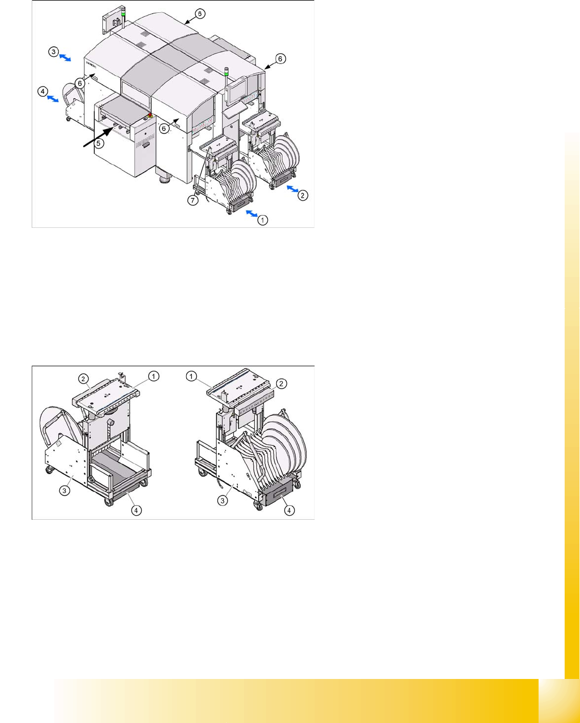
3.2.5 Changeover Table Components
3.2.5.1 Setting the Height of the CO Table
The CO table can be manually set to the following PCB transport heights
830 mm PCB transport height
900 mm PCB transport height
930 mm PCB transport height
950 mm PCB transport height
Legend:
1. CO table location 1
2. CO table location 2
3. CO table location 3
4. CO table location 4
5. Transport direction
6. The button for docking and undocking the CO
changeover tables is located under the feeder
cover flap of each CO table
7. Switch to lower the table after undocking
Legend:
1. Feeder table plate
2. Communication unit
3. Tape container
4. Waste container for tape cuttings