00195193-02 SG D4 FSE en (1).pdf - 第57页
Overview C&P12 Head DLM3 General Overview of Assemblies Student Guide SIPLACE D4 (FSE) EN 09/2006 Overview 57 3.2.7 C&P12 Head DLM3 3.2 - 9: C&P12 head Legend Option: Digital camera SS T.29 for the C&P12 …

Overview
General Overview of Assemblies Gantry
Student Guide SIPLACE D4 (FSE)
Overview EN 09/2006
56
3.2.6.3.5 Y-Axis Technical Data
Drive Direct, linear motor
Maximum speed 2.5 m/sec.
Travel path of gantries, calculated from the center of
the machine
Gantry 1 - 688.5 mm
Gantry 2 - 768.5 mm
Gantry 3 - 688.5 mm
Gantry 4 - 768.5 mm
Distance measuring system Incremental scale
Scale length 1530 mm
Resolution 1 µm
Overview
C&P12 Head DLM3 General Overview of Assemblies
Student Guide SIPLACE D4 (FSE)
EN 09/2006 Overview
57
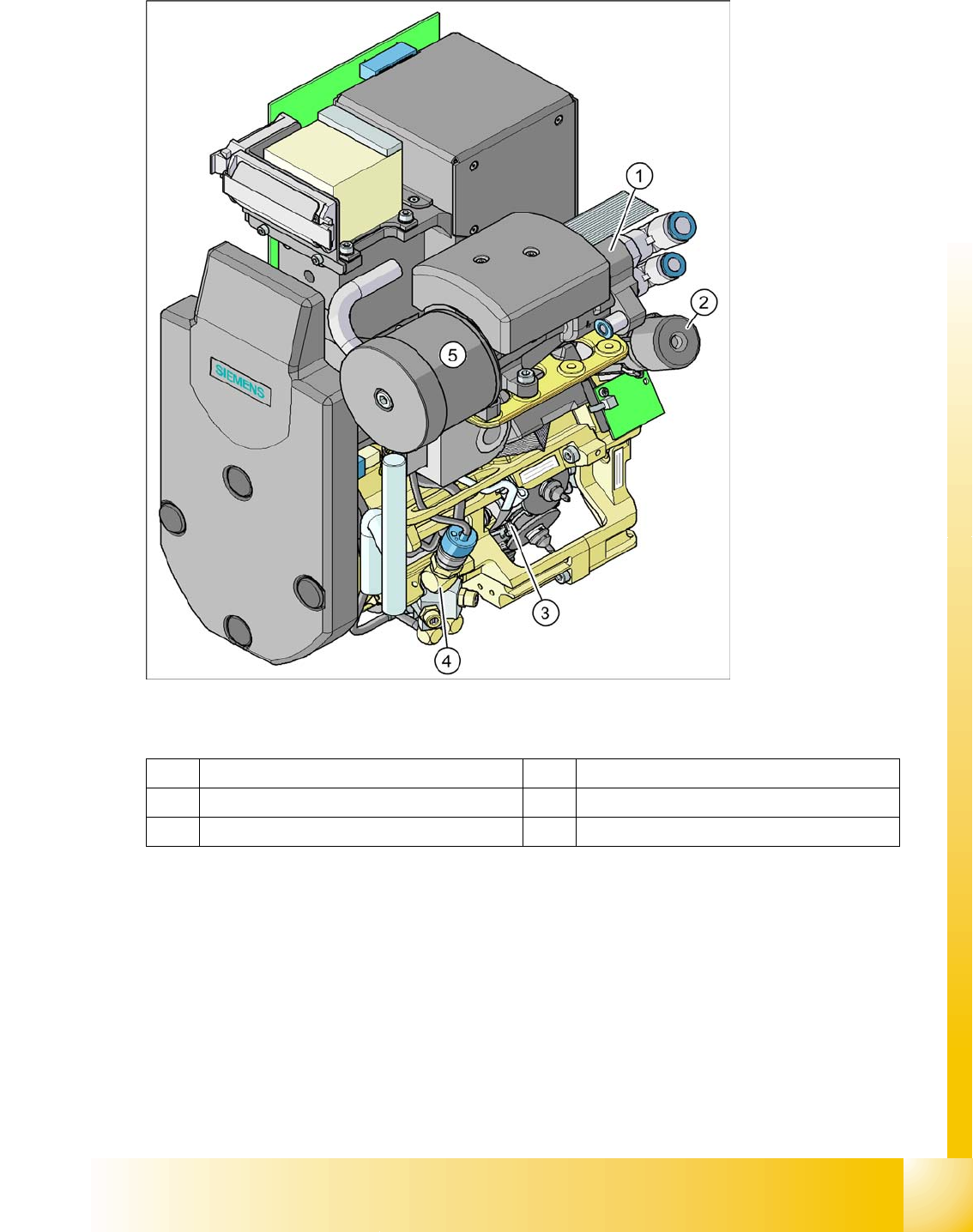
3.2.7 C&P12 Head DLM3
3.2 - 9: C&P12 head
Legend
Option: Digital camera SST.29 for the C&P12 head and CO sensor (part no. 00118021-xx) for 0201
placement.
1 Vacuum generator 4 Forced air valve
2 Turning station (DP axis) 5 Silencer
3 Star with 12 sleeves (star axis)
Overview
General Overview of Assemblies C&P12 Head DLM3
Student Guide SIPLACE D4 (FSE)
Overview EN 09/2006
58
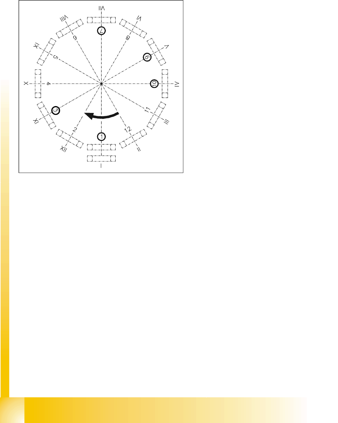
3.2.7.1 Overview of Functions for Star Stations 1 - 12
3.2.7.2 Position and Function of the Individual Star Stations
Star station 1:
Pick-up cycle
The nozzle is lowered towards the component. After a vacuum has been produced with the help of
the valve positioning function, the nozzle takes the component from the feeder module.
Placement cycle
The nozzle, together with the component, is lowered onto the PCB that has been moved into place.
The valve is positioned to cut off the supply of vacuum to the nozzle. A brief burst of air separates
the component from the nozzle and the component is placed onto the board.
Star station 3:
Reject cycle
The valve is positioned to cut off the supply of vacuum to the nozzle. Defective components are
rejected from the nozzle with a short air kiss of compressed air and are discarded.
Star station 7:
The component is optically centered.
Star station 9:
Pick-up cycle
The nozzle is rotated into the "pickup" position.
Placement cycle
The component is rotated into the correct placement angle with the help of the DP axis.
Star station 1: pickup, placement
Star station 2: no function
Star station 3: reject component
Star station 4-6: no function
Star station 7: optical centering of component
Star station 8: no function
Star station 9: rotate component
Star station 10: service position for sleeves and
nozzles
Star station 11 and 12: no function (optional
component sensor)
I - XII: Segment numbering