00195193-02 SG D4 FSE en (1).pdf - 第58页
Overview General Overview of Assemblies C&P12 Head DLM3 S tudent Guide SIPLACE D4 (FSE) Overview EN 09/2006 58 3.2.7.1 Overview of Functions for S tar S t ations 1 - 12 3.2.7.2 Position and Function of th e Individua…
Overview
C&P12 Head DLM3 General Overview of Assemblies
Student Guide SIPLACE D4 (FSE)
EN 09/2006 Overview
57
3.2.7 C&P12 Head DLM3
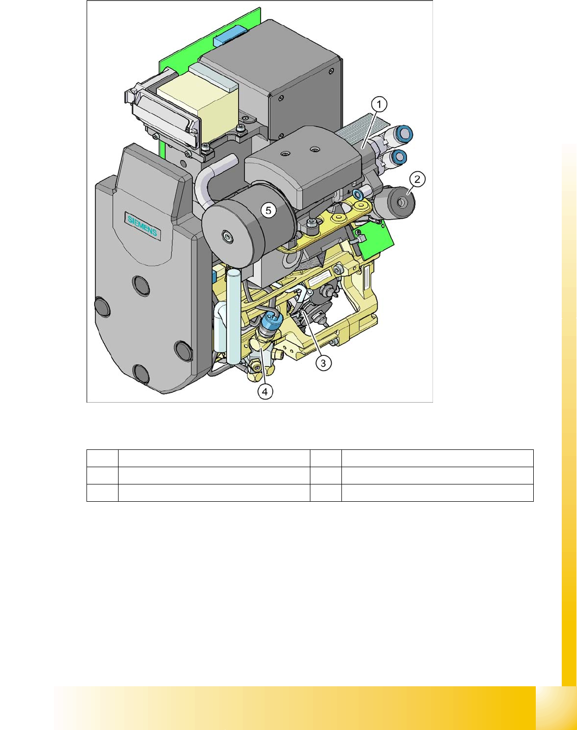
3.2 - 9: C&P12 head
Legend
Option: Digital camera SST.29 for the C&P12 head and CO sensor (part no. 00118021-xx) for 0201
placement.
1 Vacuum generator 4 Forced air valve
2 Turning station (DP axis) 5 Silencer
3 Star with 12 sleeves (star axis)
Overview
General Overview of Assemblies C&P12 Head DLM3
Student Guide SIPLACE D4 (FSE)
Overview EN 09/2006
58
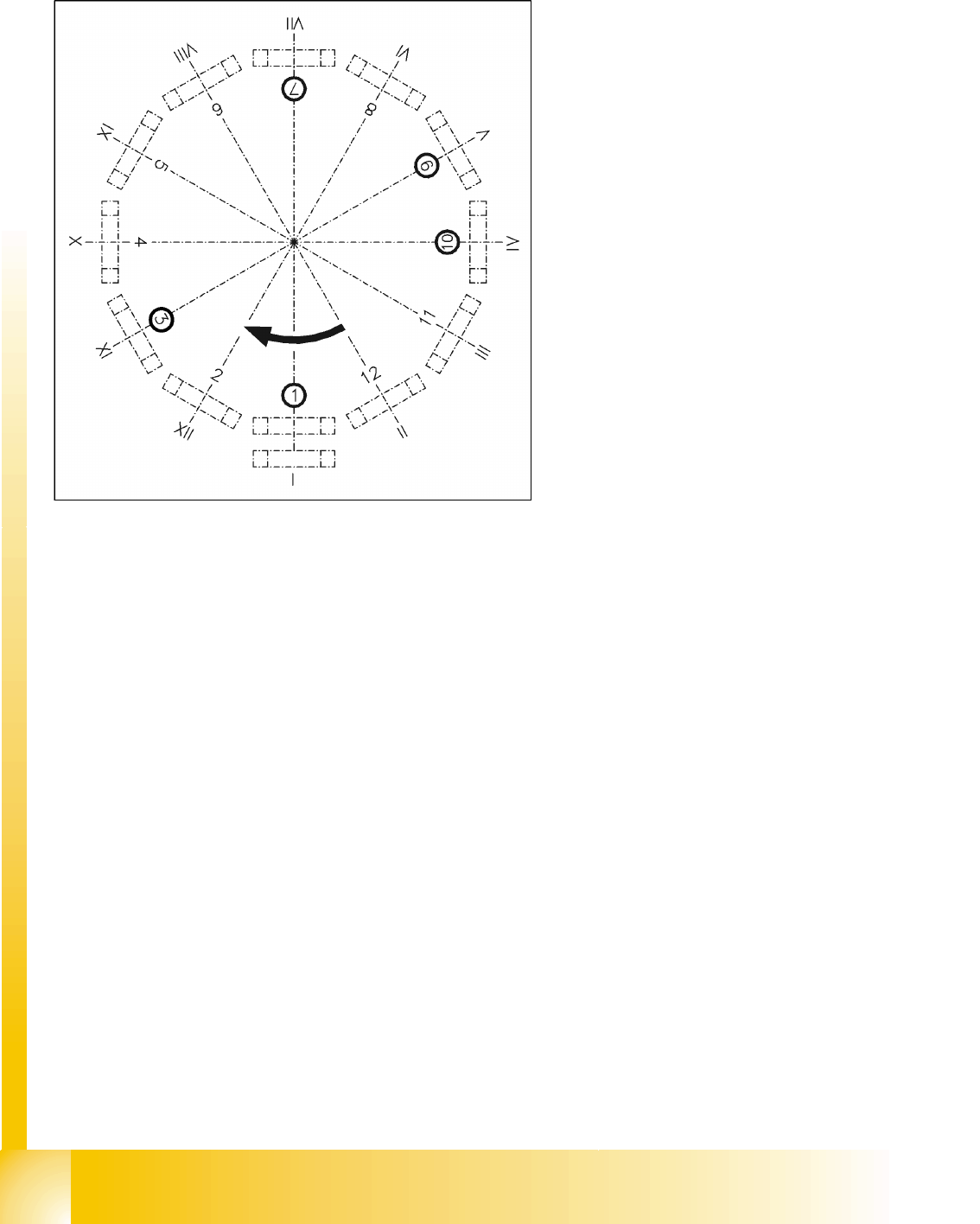
3.2.7.1 Overview of Functions for Star Stations 1 - 12
3.2.7.2 Position and Function of the Individual Star Stations
Star station 1:
Pick-up cycle
The nozzle is lowered towards the component. After a vacuum has been produced with the help of
the valve positioning function, the nozzle takes the component from the feeder module.
Placement cycle
The nozzle, together with the component, is lowered onto the PCB that has been moved into place.
The valve is positioned to cut off the supply of vacuum to the nozzle. A brief burst of air separates
the component from the nozzle and the component is placed onto the board.
Star station 3:
Reject cycle
The valve is positioned to cut off the supply of vacuum to the nozzle. Defective components are
rejected from the nozzle with a short air kiss of compressed air and are discarded.
Star station 7:
The component is optically centered.
Star station 9:
Pick-up cycle
The nozzle is rotated into the "pickup" position.
Placement cycle
The component is rotated into the correct placement angle with the help of the DP axis.
Star station 1: pickup, placement
Star station 2: no function
Star station 3: reject component
Star station 4-6: no function
Star station 7: optical centering of component
Star station 8: no function
Star station 9: rotate component
Star station 10: service position for sleeves and
nozzles
Star station 11 and 12: no function (optional
component sensor)
I - XII: Segment numbering
Overview
C&P12 Head DLM3 General Overview of Assemblies
Student Guide SIPLACE D4 (FSE)
EN 09/2006 Overview
59
Between star station 11&12
The "presence" and "height" of the component at the nozzle is checked by the CO sensor (optional).
3.2.7.3 Component Pickup and Placement
X A board is moved into the placement area of the PCB conveyor and is clamped into place.
X After fiducial measurement, the Collect&Place head picks up the components from the feeder
modules.
X The components are measured under the CO camera and rotated into the correct position in the DP
station.
X The component is placed in star station 1.
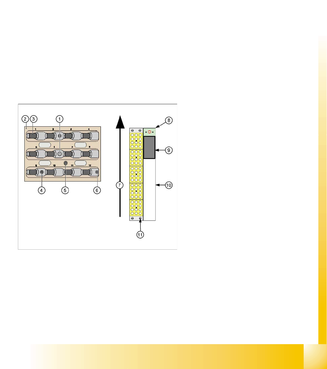
3.2.7.4 Nozzle changer for 12 segment C&P head
Optionally, a nozzle changer can be installed for each C&P head. This enables the nozzle configuration
to be changed quickly, thus allowing the Collect&Place head to be quickly adapted to the needs of the
placement process.
The nozzle changer consists of at least one and up to five magazines, each of which is equipped with
up to twelve nozzle garages. The magazines are seated on a common support and each magazine is
centered using two pins and is fixed in place with a spring hook.
Each garage can be configured with different nozzle types.
Legend:
1. Calibration fiducial
2. Locking Plate
3. Nozzle garage
4. Hole for centering pin, for exact positioning of
magazine
5. Hole for driver pin, for opening and closing of
magazine
6. Slit for centering pin, for exact positioning of
magazine
7. Transport direction
8. Nozzle reject device
9. Nozzle reject container
10. Tape duct
11. Fastening screws for nozzle changer (4x)