00195193-02 SG D4 FSE en (1).pdf - 第62页
Overview General Overview of Assemblies SIPLACE Vision S tudent Guide SIPLACE D4 (FSE) Overview EN 09/2006 62 3.2.8.1.8 Inkspot Criteria 3.2.8.2 Digit al CO Camera C&P12 (T ype 28) Methods Synthetic fiducial detect…

Overview
SIPLACE Vision General Overview of Assemblies
Student Guide SIPLACE D4 (FSE)
EN 09/2006 Overview
61
3.2.8.1.7 Fiducial Criteria
Determine 2 fiducials X/Y position, angle of twist, central PCB displacement
Determine 3 fiducials Additional: shearing, displacement separately in X and Y direction
Fiducial shapes Synthetic fiducials: circle , cross , square , rectangle , diamond , circular,
square and rectangular contours, doublecross
Pattern: any
Fiducial surface
Copper Without oxidation and soldering paste
Tin Warpage 1/10 of the structure width, with good contrast to surroundings
Dimensions of synthetic fiducials
Min. X/ Y size for circle and rectangle: 0.25 mm
Min. X/ Y size for square ring and rectangle frame: 0.3 mm
Min. X/ Y size for cross: 0.3 mm
Min. X/ Y size for doublecross: 0.5 mm
Min. X/ Y size for diamond: 0,35 mm
Min. frame width for square ring and rectangle frame: 0,1 mm
Min. bar width/bar spacing for cross, doublecross: 0,1 mm
Max. X/ Y size for all fiducial shapes: 3 mm
Max. bar width/bar spacing for cross, doublecross: 1,5 mm
Min. general tolerances: 2% of nominal
dimensions
Max. general tolerances: 20% of nominal
dimensions
Dimensions of templates
Min. size 0.5 mm
Max. size 3 mm
Fiducial surroundings Space is not needed around the fiducials, provided there are no other similar
fiducial structures in the search field.
Overview
General Overview of Assemblies SIPLACE Vision
Student Guide SIPLACE D4 (FSE)
Overview EN 09/2006
62
3.2.8.1.8 Inkspot Criteria
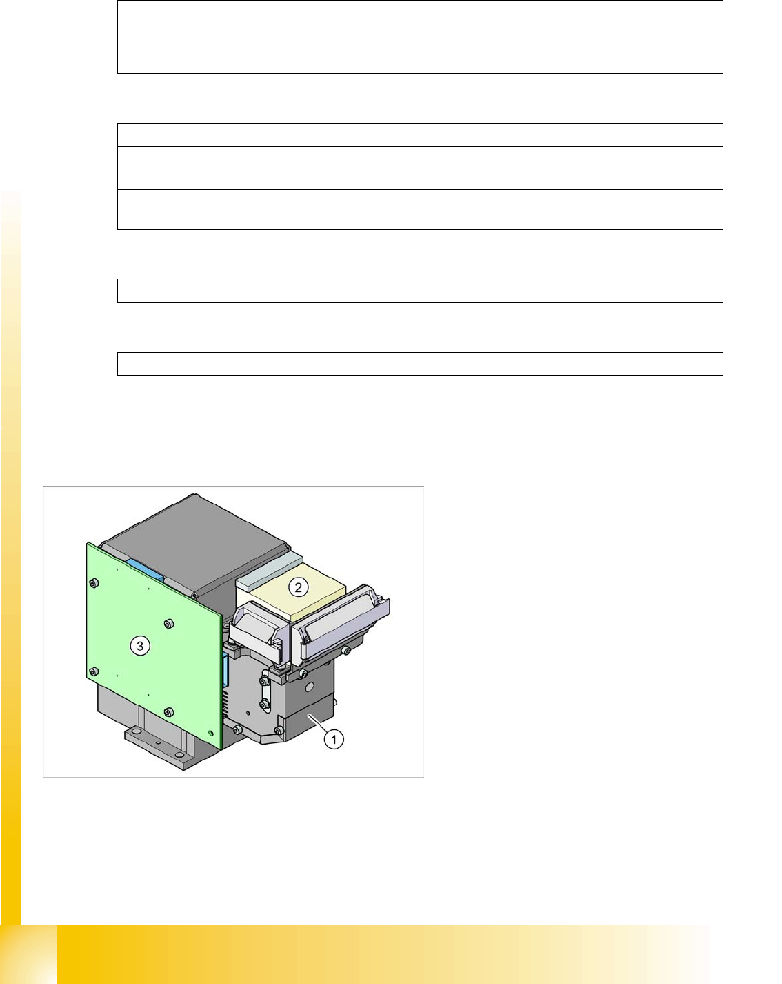
3.2.8.2 Digital CO Camera C&P12 (Type 28)
Methods Synthetic fiducial detection procedures
Middle gray value
Histogram method
Template matching
Size of fiducial shapes or structures
Synthetic fiducials
For dimensions of synthetic fiducials, see
Section 3.2.8.1.7 Fiducial Cri-
teria [J 58]
.
Other methods Min. 0,3 mm
max. 5 mm
Cover material Covers well
Recognition time Depending on method, 20 ms - 0.2 s
Legend:
1. CO camera optics and illumination
2. Camera amplifier
3. Illumination control
Overview
SIPLACE Vision General Overview of Assemblies
Student Guide SIPLACE D4 (FSE)
EN 09/2006 Overview
63
3.2.8.2.9 Technical data
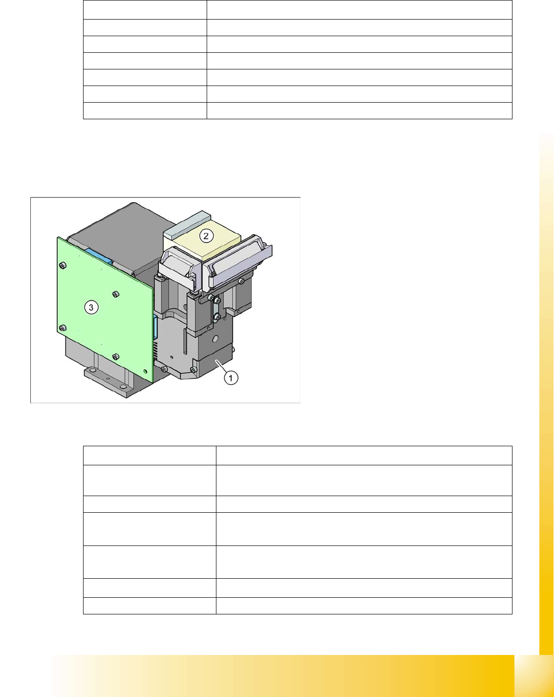
3.2.8.3 CO Camera C&P12 (optional, type 29)
3.2.8.3.10 Technical data
Component dimensions
0.5 x 0.5 mm
2
to 18.7 x 18.7 mm
2
Component range 0402 to PLCC44 incl. BGA, µBGA, flip-chip, TSOP, QFP, SO to SO32, DRAM
Min. lead pitch 0.5 mm
Min. ball pitch 0.45 mm
Min. ball diameter 0.25 mm
Field of vision 24.5 x 24.5 mm2
Method of illumination Front-lighting (5 levels, programable as required)
Legend:
1. CO camera optics and illumination
2. Camera amplifier
3. Illumination control
Component dimensions
0.3 x 0.3 mm
2
to 27 x 27 mm
2
Component range
0201 to 27 x 27 mm
2
PLCC, SO, QFP, TSDP, SOT, MELF, CHIP, IC, BGA
Min. lead pitch 0.3 mm
Min. ball pitch
0.25 mm for CO < 18 x 18 mm
2
0.35 mm for CO ≥ 18 x 18 mm
2
Min. ball diameter
0.14 mm for CO < 18 x 18 mm
2
0.2 mm for CO ≥ 18 x 18 mm
2
Field of vision
31 x 31 mm
2
Method of illumination Front-lighting (5 levels, programable as required)