00195193-02 SG D4 FSE en (1).pdf - 第63页
Overview SIPLACE Vision General Overview of Assemblies Student Guide SIPLACE D4 (FSE) EN 09/2006 Overview 63 3.2.8.2.9 T echnical dat a 3.2.8.3 CO Camera C&P12 (optional, type 29) 3.2.8.3.10 T echnical dat a Componen…
Overview
General Overview of Assemblies SIPLACE Vision
Student Guide SIPLACE D4 (FSE)
Overview EN 09/2006
62
3.2.8.1.8 Inkspot Criteria
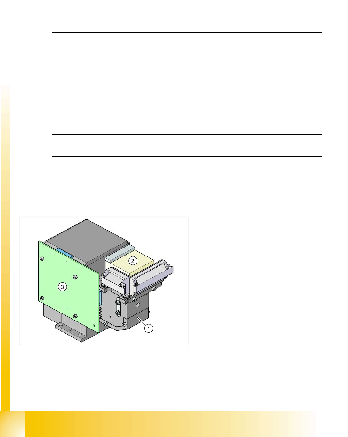
3.2.8.2 Digital CO Camera C&P12 (Type 28)
Methods Synthetic fiducial detection procedures
Middle gray value
Histogram method
Template matching
Size of fiducial shapes or structures
Synthetic fiducials
For dimensions of synthetic fiducials, see
Section 3.2.8.1.7 Fiducial Cri-
teria [J 58]
.
Other methods Min. 0,3 mm
max. 5 mm
Cover material Covers well
Recognition time Depending on method, 20 ms - 0.2 s
Legend:
1. CO camera optics and illumination
2. Camera amplifier
3. Illumination control
Overview
SIPLACE Vision General Overview of Assemblies
Student Guide SIPLACE D4 (FSE)
EN 09/2006 Overview
63
3.2.8.2.9 Technical data
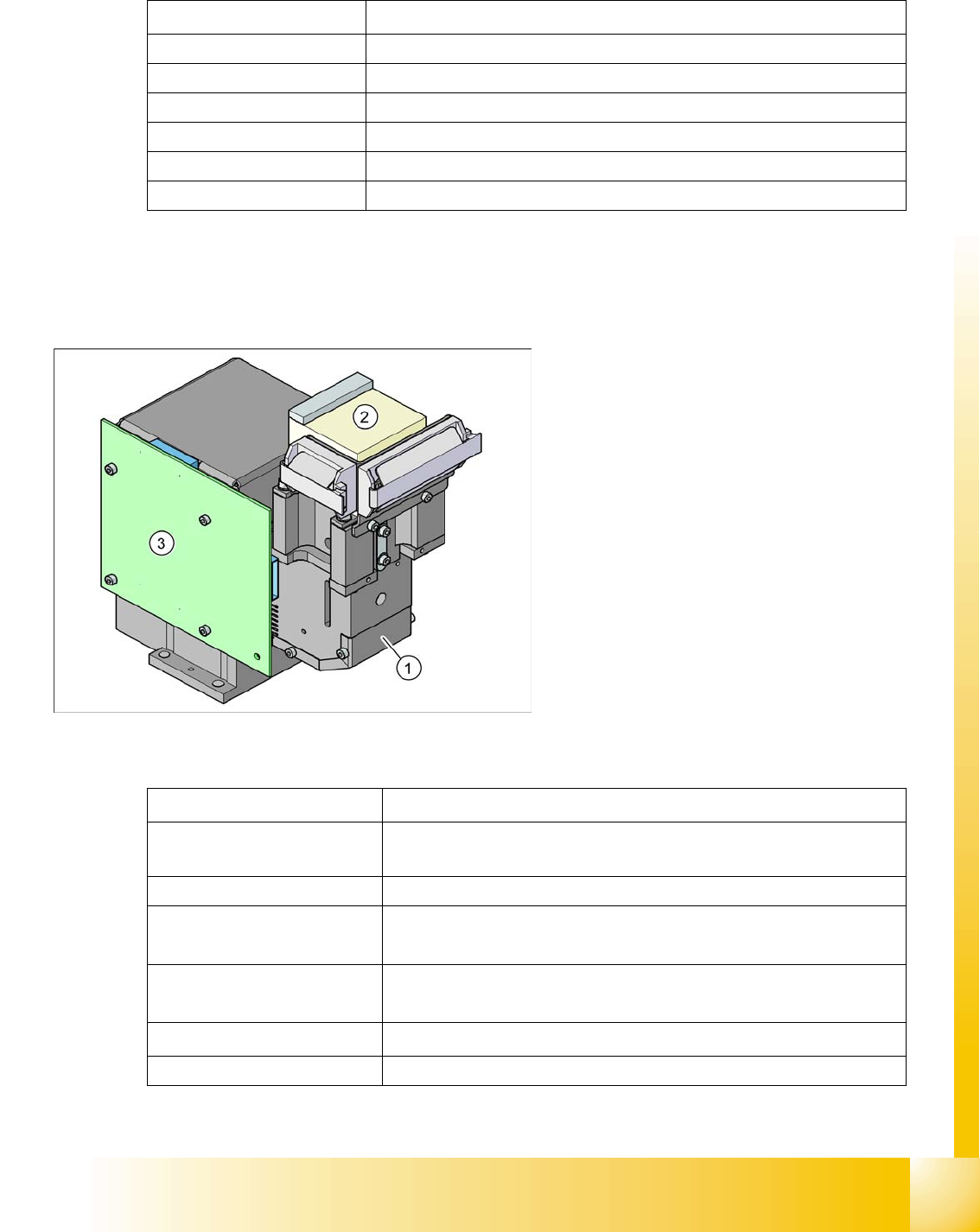
3.2.8.3 CO Camera C&P12 (optional, type 29)
3.2.8.3.10 Technical data
Component dimensions
0.5 x 0.5 mm
2
to 18.7 x 18.7 mm
2
Component range 0402 to PLCC44 incl. BGA, µBGA, flip-chip, TSOP, QFP, SO to SO32, DRAM
Min. lead pitch 0.5 mm
Min. ball pitch 0.45 mm
Min. ball diameter 0.25 mm
Field of vision 24.5 x 24.5 mm2
Method of illumination Front-lighting (5 levels, programable as required)
Legend:
1. CO camera optics and illumination
2. Camera amplifier
3. Illumination control
Component dimensions
0.3 x 0.3 mm
2
to 27 x 27 mm
2
Component range
0201 to 27 x 27 mm
2
PLCC, SO, QFP, TSDP, SOT, MELF, CHIP, IC, BGA
Min. lead pitch 0.3 mm
Min. ball pitch
0.25 mm for CO < 18 x 18 mm
2
0.35 mm for CO ≥ 18 x 18 mm
2
Min. ball diameter
0.14 mm for CO < 18 x 18 mm
2
0.2 mm for CO ≥ 18 x 18 mm
2
Field of vision
31 x 31 mm
2
Method of illumination Front-lighting (5 levels, programable as required)

Overview
General Overview of Assemblies Conveyor System
Student Guide SIPLACE D4 (FSE)
Overview EN 09/2006
64
3.2.9 Conveyor System
3.2.9.1 General
The standard machine is equipped with a single PCB conveyor. A dual PCB conveyor system is
optionally available. Depending on individual requirements, either the left or right conveyor side can be
selected as the fixed conveyor side.
In the Processing Area (PA1 or PA2), the PCB board will be clamped from the bottom side against the
fixed holder on the conveyor system. Therefore, the space between the upper side of the board and the
placement head remains the same for each board and no longer depends on the thickness of the board.
This means that the placement performance also no longer depends on the board thickness. The PCB
fiducial centering can also be optimized. The consistent space between the board upper edge and the
PCB camera means that the PCB camera is always optimally focussed on the upper side of the board.
The PCB fiducial shape is optimally imaged on the CCD chip of the PCB camera.
The PCB transport in the SIPLACE machine is configured so that the C&P12 head can place
components up to a maximum height of 6 mm.
The machine height can be adjusted so that the machine can also be integrated into lines with transport
heights of 830, 900, 930 or 950 mm. Communication between the PCB conveyors of the different
machines is provided with the help of a SMEMA or SIEMENS (optional) interface.
The transportation of the boards is monitored and controlled by light barriers, consisting of a transmitter
and a receiver module. Once the board has reached the placement area and the board has been
recognized by the light barrier, the speed of the conveyor belt is reduced. The board is stopped with the
help of a laser beam and is then clamped into place from below.
Clamping
The PCB is lifted for placement of components and pressed up against the PCB clamping rail. When the
lifting table rises the PCB and the complete conveyor drive unit is lifted up to the clamping position. This
method enables the placement surface to remain in the same position, irrespective of the board
thickness.
Boards with a length up to 368 mm are clamped into place in the relevant placement area. Clamping
does not take place on the input and output conveyor. However, boards with lengths above 368 mm are
placed up to a length of 610 mm on the conveyor belt and are only supported by the lifting table in the
placement area.
Width adjustment
The width is adjusted by means of a motor as programmed. For dual conveyor systems, differing widths
can be set for the two conveyor belts. The width adjustment uses a stepping motor, meaning that the
new PCB width can be set independently of other machine components (e.g. the Y-gantry). The
proximity switch on the conveyor side is no longer needed.
The PCB width is adjusted via two adjustment units (pneumatic cylinder), which are installed under the
input and output conveyors. The stepping motor moves the two adjustment units synchronously back
and forth, through the use of ball bearing spindles and a toothed belt.