00195193-02 SG D4 FSE en (1).pdf - 第65页
Overview Conveyor System General Overview of Assemblies Student Guide SIPLACE D4 (FSE) EN 09/2006 Overview 65 Board control In the conveyor The boards are checked with the help of light ba rrie rs (transmitte r and recei…

Overview
General Overview of Assemblies Conveyor System
Student Guide SIPLACE D4 (FSE)
Overview EN 09/2006
64
3.2.9 Conveyor System
3.2.9.1 General
The standard machine is equipped with a single PCB conveyor. A dual PCB conveyor system is
optionally available. Depending on individual requirements, either the left or right conveyor side can be
selected as the fixed conveyor side.
In the Processing Area (PA1 or PA2), the PCB board will be clamped from the bottom side against the
fixed holder on the conveyor system. Therefore, the space between the upper side of the board and the
placement head remains the same for each board and no longer depends on the thickness of the board.
This means that the placement performance also no longer depends on the board thickness. The PCB
fiducial centering can also be optimized. The consistent space between the board upper edge and the
PCB camera means that the PCB camera is always optimally focussed on the upper side of the board.
The PCB fiducial shape is optimally imaged on the CCD chip of the PCB camera.
The PCB transport in the SIPLACE machine is configured so that the C&P12 head can place
components up to a maximum height of 6 mm.
The machine height can be adjusted so that the machine can also be integrated into lines with transport
heights of 830, 900, 930 or 950 mm. Communication between the PCB conveyors of the different
machines is provided with the help of a SMEMA or SIEMENS (optional) interface.
The transportation of the boards is monitored and controlled by light barriers, consisting of a transmitter
and a receiver module. Once the board has reached the placement area and the board has been
recognized by the light barrier, the speed of the conveyor belt is reduced. The board is stopped with the
help of a laser beam and is then clamped into place from below.
Clamping
The PCB is lifted for placement of components and pressed up against the PCB clamping rail. When the
lifting table rises the PCB and the complete conveyor drive unit is lifted up to the clamping position. This
method enables the placement surface to remain in the same position, irrespective of the board
thickness.
Boards with a length up to 368 mm are clamped into place in the relevant placement area. Clamping
does not take place on the input and output conveyor. However, boards with lengths above 368 mm are
placed up to a length of 610 mm on the conveyor belt and are only supported by the lifting table in the
placement area.
Width adjustment
The width is adjusted by means of a motor as programmed. For dual conveyor systems, differing widths
can be set for the two conveyor belts. The width adjustment uses a stepping motor, meaning that the
new PCB width can be set independently of other machine components (e.g. the Y-gantry). The
proximity switch on the conveyor side is no longer needed.
The PCB width is adjusted via two adjustment units (pneumatic cylinder), which are installed under the
input and output conveyors. The stepping motor moves the two adjustment units synchronously back
and forth, through the use of ball bearing spindles and a toothed belt.

Overview
Conveyor System General Overview of Assemblies
Student Guide SIPLACE D4 (FSE)
EN 09/2006 Overview
65
Board control In the conveyor
The boards are checked with the help of light barriers (transmitter and receiver). The transmitter is
located below the conveyor belt and the receiver opposite to it, above the conveyor belt. The light
barriers stop the board in the input conveyor, intermediate and output conveyors.
The light barrier in the placement areas starts the braking process via the DC motor and switches the
laser (stopper) on. The board moves at reduced speed, within a fixed time window (100 ms) , until it
reaches the stopping position (laser). The braking profile is adjusted to the weight of the board (software-
controlled). This guarantees a consistent transport time, irrespective of the board used
Board stopper
In the placement area, the board is stopped by the laser light barrier. This laser light barrier recognizes
the front edge of the board and stops it. This prevents the board from hitting the mechanical end stop.
The positioning accuracy for the board is +/-0.5 mm.
An optional second, mechanical stopper is available for long boards, with lengths up to 610 mm.
Lifting table
Each placement area has one or two independently working lifting tables (single/dual conveyor). The
lifting table is driven indirectly via a pneumatic cylinder, with 5/2 direction control valve. Different PCB
thicknesses are automatically compensated. The vertical guidance for the lifting table plate (up/down) is
defined at four points. The travel distance is determined by a measurement system.
The top position is controlled by the measurement system, with the help of an incremental encoder and
a defined time window. The conveyor motor checks whether the board has been successfully clamped
into place.
The bottom position is checked by the measuring system, with the help of a proximity switch on the
pneumatic cylinder and a defined time window.
The space below the board is 40 mm.
The "old" 74 mm high, red board supports are no longer supported by the HF and SIPLACE X/D
machines. Instead, use the black (94 mm) PCB supports.
The dual conveyor can also be used as a single conveyor, if the conveyor sides from lane 2 are moved
together (flexible dual conveyor).
Overview
General Overview of Assemblies Conveyor System
Student Guide SIPLACE D4 (FSE)
Overview EN 09/2006
66
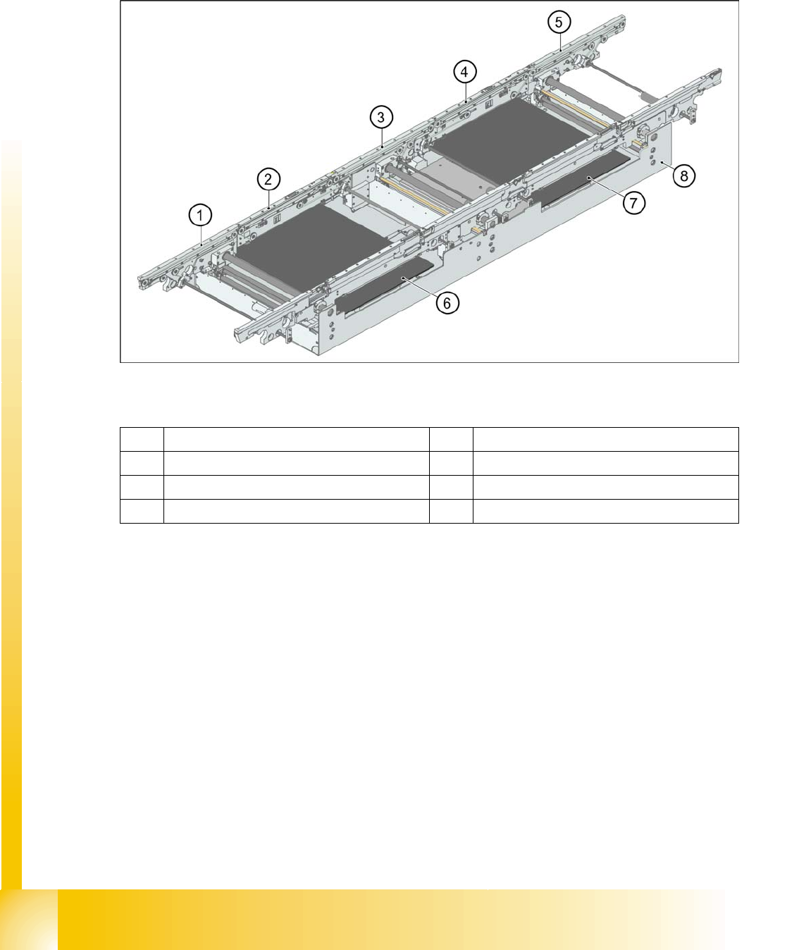
3.2.9.2 Single Conveyor Construction
The single conveyor system consists of an input conveyor, two placement areas, the intermediate
conveyor and the output conveyor. Each conveyor has automatic width adjustment and two lifting tables
to clamp the PCB in place.
3.2 - 10: Board conveyor construction
Legend
1 Eingabeband 5 Ausgabeband
2 Processing conveyor 1 6 Lifting table 1
3 Intermediate conveyor 7 Lifting table 2
4 Processing conveyor 2 8 Mounting frame