00195193-02 SG D4 FSE en (1).pdf - 第66页
Overview General Overview of Assemblies Conveyor System S tudent Guide SIPLACE D4 (FSE) Overview EN 09/2006 66 3.2.9.2 Single Conveyor Construction The single conveyor sy stem consists of an inpu t conveyor, two placemen…

Overview
Conveyor System General Overview of Assemblies
Student Guide SIPLACE D4 (FSE)
EN 09/2006 Overview
65
Board control In the conveyor
The boards are checked with the help of light barriers (transmitter and receiver). The transmitter is
located below the conveyor belt and the receiver opposite to it, above the conveyor belt. The light
barriers stop the board in the input conveyor, intermediate and output conveyors.
The light barrier in the placement areas starts the braking process via the DC motor and switches the
laser (stopper) on. The board moves at reduced speed, within a fixed time window (100 ms) , until it
reaches the stopping position (laser). The braking profile is adjusted to the weight of the board (software-
controlled). This guarantees a consistent transport time, irrespective of the board used
Board stopper
In the placement area, the board is stopped by the laser light barrier. This laser light barrier recognizes
the front edge of the board and stops it. This prevents the board from hitting the mechanical end stop.
The positioning accuracy for the board is +/-0.5 mm.
An optional second, mechanical stopper is available for long boards, with lengths up to 610 mm.
Lifting table
Each placement area has one or two independently working lifting tables (single/dual conveyor). The
lifting table is driven indirectly via a pneumatic cylinder, with 5/2 direction control valve. Different PCB
thicknesses are automatically compensated. The vertical guidance for the lifting table plate (up/down) is
defined at four points. The travel distance is determined by a measurement system.
The top position is controlled by the measurement system, with the help of an incremental encoder and
a defined time window. The conveyor motor checks whether the board has been successfully clamped
into place.
The bottom position is checked by the measuring system, with the help of a proximity switch on the
pneumatic cylinder and a defined time window.
The space below the board is 40 mm.
The "old" 74 mm high, red board supports are no longer supported by the HF and SIPLACE X/D
machines. Instead, use the black (94 mm) PCB supports.
The dual conveyor can also be used as a single conveyor, if the conveyor sides from lane 2 are moved
together (flexible dual conveyor).
Overview
General Overview of Assemblies Conveyor System
Student Guide SIPLACE D4 (FSE)
Overview EN 09/2006
66
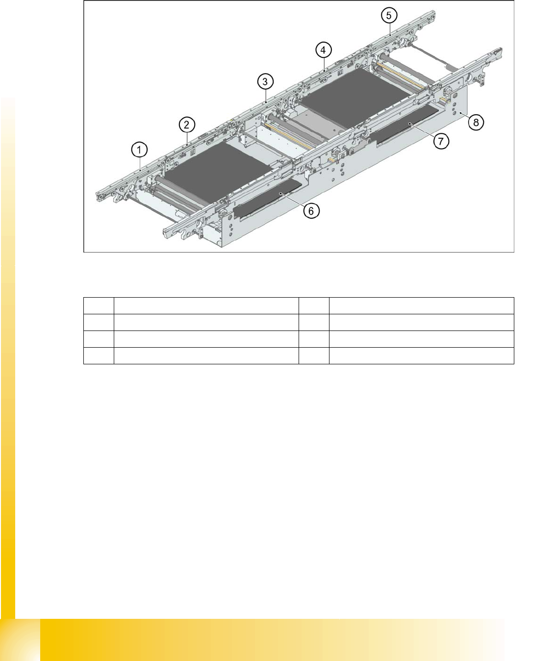
3.2.9.2 Single Conveyor Construction
The single conveyor system consists of an input conveyor, two placement areas, the intermediate
conveyor and the output conveyor. Each conveyor has automatic width adjustment and two lifting tables
to clamp the PCB in place.
3.2 - 10: Board conveyor construction
Legend
1 Eingabeband 5 Ausgabeband
2 Processing conveyor 1 6 Lifting table 1
3 Intermediate conveyor 7 Lifting table 2
4 Processing conveyor 2 8 Mounting frame
Overview
Conveyor System General Overview of Assemblies
Student Guide SIPLACE D4 (FSE)
EN 09/2006 Overview
67
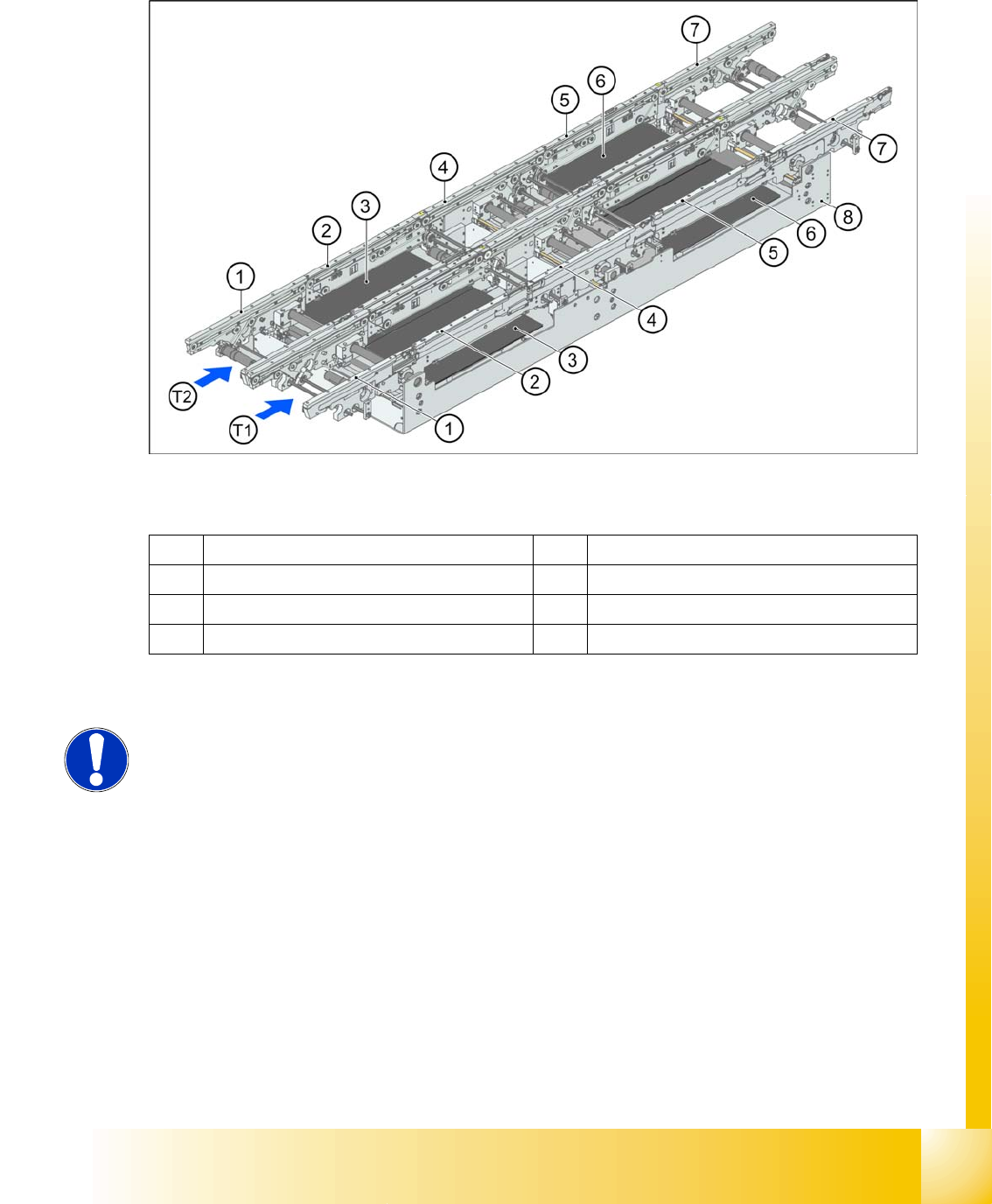
3.2.9.3 Dual Conveyor Construction
The dual conveyor has two conveyor lanes (1 and 2). In the standard model, the fixed conveyor side is
on the right side of each lane. This fixed conveyor side can be easily changed to the left.
3.2 - 11: Dual conveyor construction
Legend
1 Eingabeband 5 Processing conveyor 2
2 Processing conveyor 1 6 Lifting table 2
3 Lifting table 1 7 Ausgabeband
4 Intermediate conveyor 8 Mounting frame
NOTE:
For options concerning single and dual conveyors, refer to Chapter Conveyor.