00195193-02 SG D4 FSE en (1).pdf - 第75页
Communication and Control Network Machine Controller Communication S tudent Guide SIPLACE D4 (FSE) Communication and Control EN 09/2006 74 4.2.4 Machine Contro ller Communication When calculating th e pickup coordinates …
Communication and Control
Communication on placement machine Network
Student Guide SIPLACE D4 (FSE)
EN 09/2006 Communication and Control
73
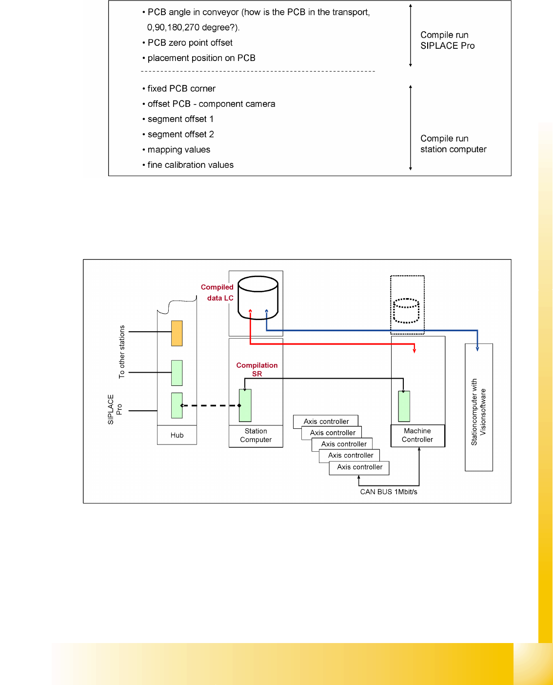
4.2.2.2 Compiling the placement position (X/Y coordinates and angle)
The following values are taken into account during calculation of the theoretical placement position:
4.2.3 Communication on placement machine
The placement data files, stored on the hard drive, are compiled at the station computer for the machine
controller. This compiling procedure adds the calibrated values, determined during calibration in
SITEST, to the pick up and placement data.
4.2 - 4: Communication on placement machine
Communication and Control
Network Machine Controller Communication
Student Guide SIPLACE D4 (FSE)
Communication and Control EN 09/2006
74
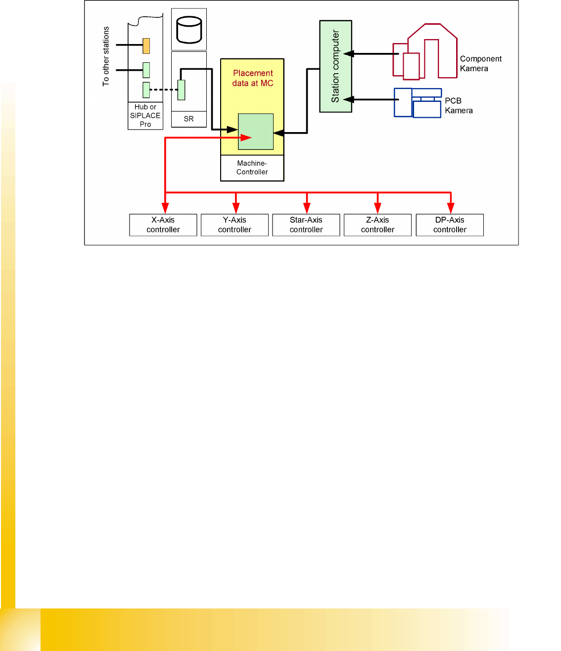
4.2.4 Machine Controller Communication
When calculating the pickup coordinates, the machine controller adds the pickup correction values
(previously known as pickup offsets) to the pickup coordinates. When calculating the placement
coordinates, the machine controller adds the board position and component correction values to the
placement coordinates.
4.2 - 5: Communication with MC
Communication and Control
Machine Controller Communication CAN Bus
Student Guide SIPLACE D4 (FSE)
EN 09/2006 Communication and Control
75
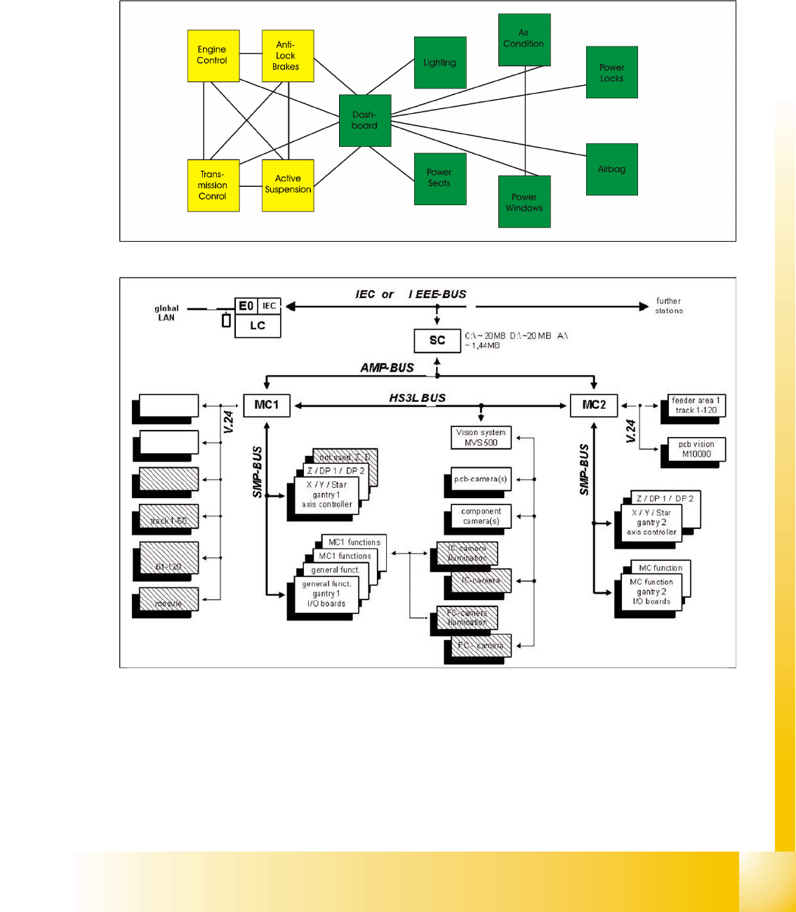
4.3 CAN Bus
The development of Controller Area Networks began as modern vehicles were controlled, monitored and
equipped with electronic controls and comfort features. Examples of such devices include engine
management systems, active suspension, ABS, gear control, lighting control, air conditioning, airbags
and central locking.
4.3 - 1: Communication via cable connection
4.3 - 2: Communication e.g. on Siplace S15 machine
To improve the behavior of the vehicle even further, it was necessary for the different control systems
(and their sensors) to exchange information. This was usually done by discrete interconnection of the
different systems (i.e. point to point wiring). The requirement for information exchange has then grown
to such an extent that a cable network with a length of up to several miles and many connectors was
required. This produced growing problems concerning material cost, production time and reliability.
The solution to this problem was the connection of the control systems via a serial bus system. This bus
had to fulfill some special requirements due to its usage in a vehicle. With the use of CAN, point-to-point