00195193-02 SG D4 FSE en (1).pdf - 第93页
Communication and Control CAN Bus Communication Siplace Vision S tudent Guide SIPLACE D4 (FSE) Communication and Control EN 09/2006 92 4.3.8 Communicatio n Siplace Vision The communication betwee n the computers is carri…
Communication and Control
CAN Bus Communication with Axis Controller CAN Bus
Student Guide SIPLACE D4 (FSE)
EN 09/2006 Communication and Control
91
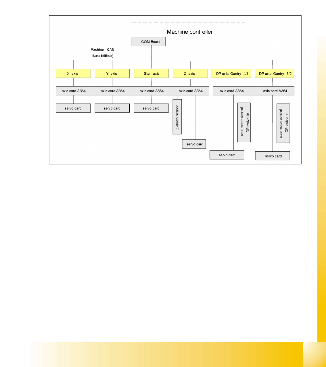
4.3.7 CAN Bus Communication with Axis Controller
In previous Siplace placement machines, the communication and data flow between axis controller and
machine controller was achieved using the SMP bus. From the HF machine generation onwards, the
SMP bus is no longer used with the axis system.
The communication between the axis controller modules is now achieved using the CAN Bus. All the
information exchanged between these modules is transmitted via the CAN bus (e.g. axis parameters,
target position, end position signal ...). This means that the number of individual telegrams increases
significantly over time, compared to the amount of data in older machine generations.
4.3 - 17: Overview axis controller
Communication and Control
CAN Bus Communication Siplace Vision
Student Guide SIPLACE D4 (FSE)
Communication and Control EN 09/2006
92
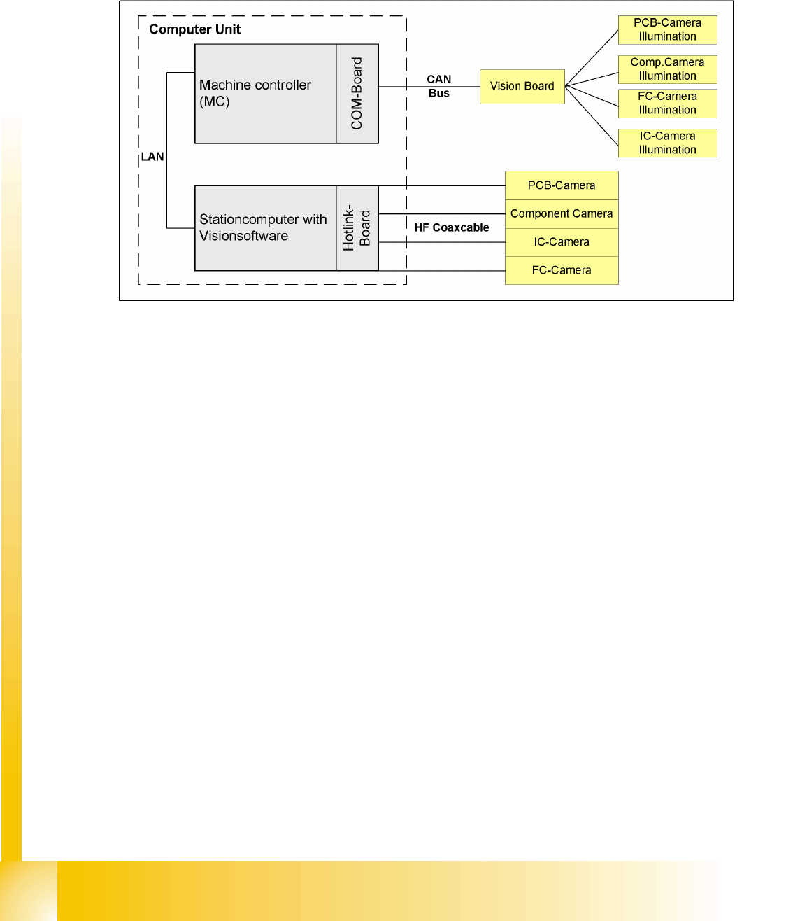
4.3.8 Communication Siplace Vision
The communication between the computers is carried out via LAN cables. The MC sends the commands
for the image acquisition to the vision computer and receives the result of the measuring. The MC also
sends the illumination values for the corresponding CSs. The taken pictures are sent digitally via the Hot
link card to the vision computer. These evaluated pictures are sent to the MC.
4.3 - 18: Overview Siplace Vision
Communication and Control
Communication Siplace Vision CAN Bus
Student Guide SIPLACE D4 (FSE)
EN 09/2006 Communication and Control
93
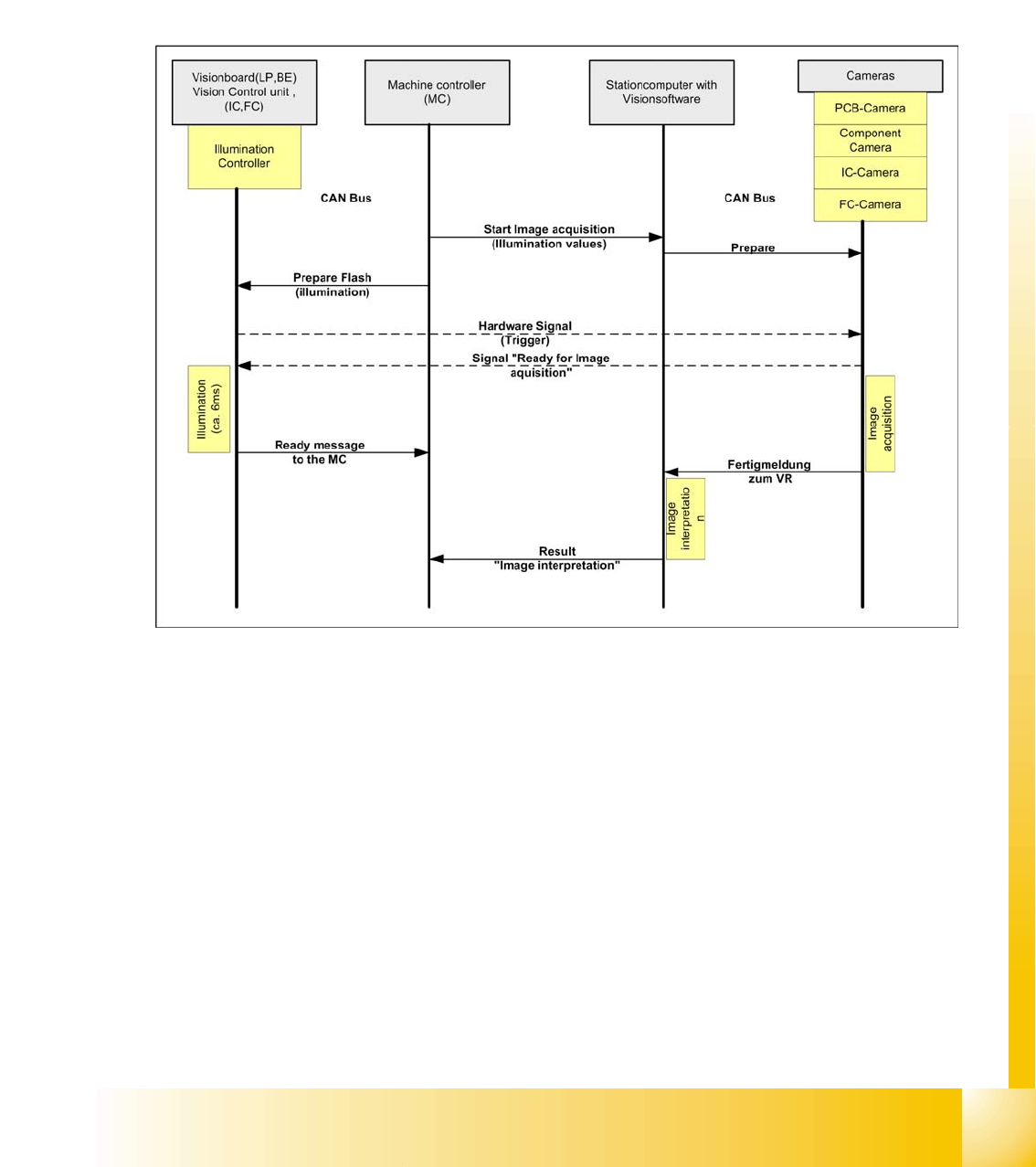
4.3.8.1 Communication during a image acquisition
The main communication between the vision system and machinecontroller is the transmission of
illumination values. These values, stored in the CS, are sent via the CAN bus to the camera concerned.
When the camera is needed to take a picture, it will be activated by a trigger signal. From this moment
on the row of LEDs which provide the different illumination levels light dependant on the illumination
value 0-255. This illumination value can have 0 = dark up to 255 = bright. The length of the illumination
period is set by using a value between 0 and 255.
The maximum length of illumination is limited to 6 ms.
4.3 - 19: Time sequence from up to down for the communication image acquisition