00195193-02 SG D4 FSE en (1).pdf - 第95页
Communication and Control Board type recognition What does it mean board type recognition? S tudent Guide SIPLACE D4 (FSE) Communication and Control EN 09/2006 94 4.4 Board type recognition 4.4.1 What does it mean board …
Communication and Control
Communication Siplace Vision CAN Bus
Student Guide SIPLACE D4 (FSE)
EN 09/2006 Communication and Control
93
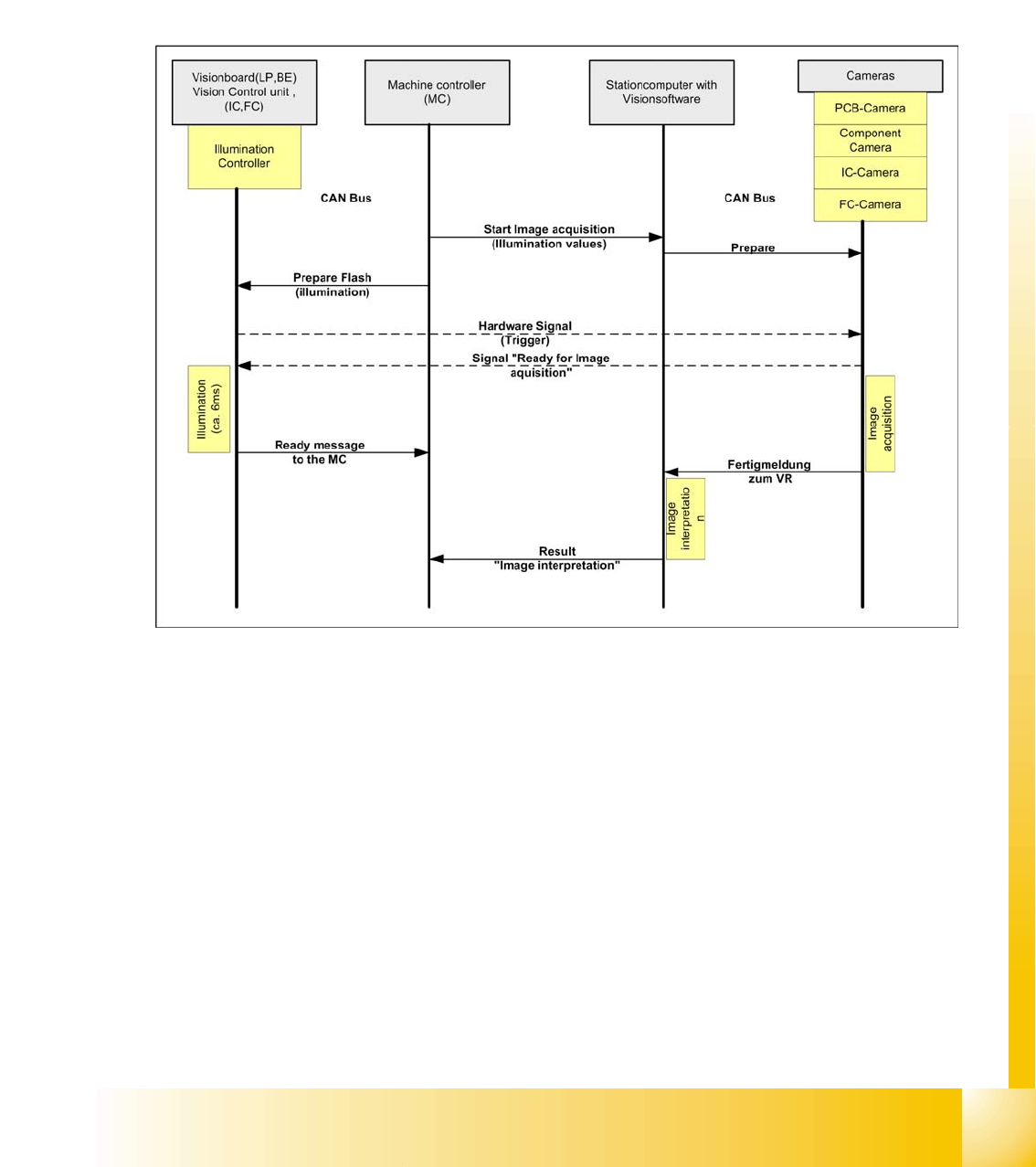
4.3.8.1 Communication during a image acquisition
The main communication between the vision system and machinecontroller is the transmission of
illumination values. These values, stored in the CS, are sent via the CAN bus to the camera concerned.
When the camera is needed to take a picture, it will be activated by a trigger signal. From this moment
on the row of LEDs which provide the different illumination levels light dependant on the illumination
value 0-255. This illumination value can have 0 = dark up to 255 = bright. The length of the illumination
period is set by using a value between 0 and 255.
The maximum length of illumination is limited to 6 ms.
4.3 - 19: Time sequence from up to down for the communication image acquisition

Communication and Control
Board type recognition What does it mean board type recognition?
Student Guide SIPLACE D4 (FSE)
Communication and Control EN 09/2006
94
4.4 Board type recognition
4.4.1 What does it mean board type recognition?
The board type recognition is an ID (identification number), which is saved in an EEPROM. These ID‘s
identify the boards (head interface, headadapter,...) in the machine via software. Each board which
communicates with a TQM module, has an EEPROM with a unique ID. These board type ID will be read
and checked from the BIOS in the TQM Module.
4.4.1.1 Why we integrate the board type recognition?
The introduction of the board type recognition has the advantage, that only one BIOS version for all TQM
modules which are installed on all machines subsystems is used.
Benefits:
simple to use for developer, set up engineer and service engineer
updates only for one Bios version for the developer
Storage, one SAP number for TQM modules (16 bit processor)
The introduction of one BIOS version on the TQM Modules for the different Subsystems was necessary
for the option Head Modularity.
4.4.1.2 Functional description
During the booting phase, the TQM module BIOS sends a request for the board ID and thereby
recognizes which boards are connected for the placement head used or on which board the TQM
module is used. If all IDs are recognized and if they are all plausible, the application software will be
loaded. The station software (with SW 601.02) will give an error message, if it does not recognize the ID
or if it is not a plausible ID. At the moment the error will be appears only on the 7 segment display of the
TQM Moduls.
4.4.1.3 Error description:
When the BIOS and Application software are downloaded and the BIOS is unable to recognize one ID,
it will give an error on the seven segment display for a short time. The error message appears 3 times,
after that the application software starts up. The machine still starts up and can produce. If the BIOS is
unable to recognize more than one ID, the TQM module in the BIOS stops with an error code on the 7
segment display. The machine will not boot and an error message will appear at the station and on the
7-segment display of the TQM module (see error list).
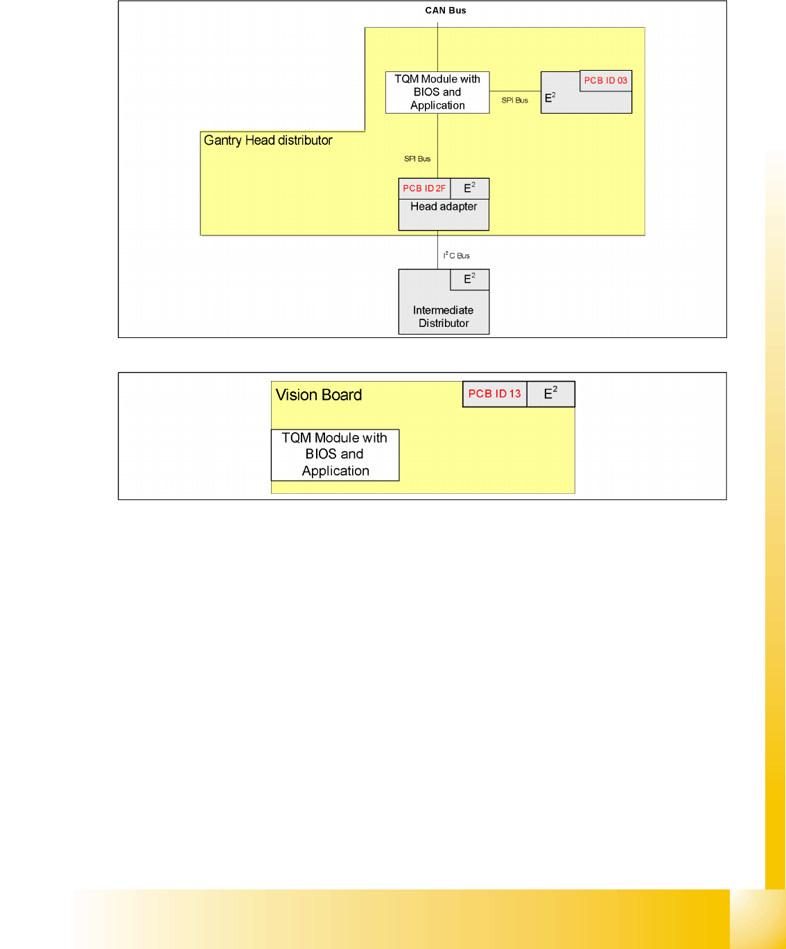
The following ID‘s are saved in the PCB‘s EEPROM:
NOTE:
Board recognition has nothing to do with the recognition of boards to be placed,
by the option
PCB barcode
option.
Communication and Control
What does it mean board type recognition? Board type recognition
Student Guide SIPLACE D4 (FSE)
EN 09/2006 Communication and Control
95
SIPLACE D series:
Gantry head distributor
Vision board
4.4 - 1: Overview of board IDs, checked by the TQM module (SIPLACE D)
4.4 - 2: Board IDs for Vision boards (SIPLACE D)