00195193-02 SG D4 FSE en (1).pdf - 第97页
Communication and Control Board type recognition What does it mean board type recognition? S tudent Guide SIPLACE D4 (FSE) Communication and Control EN 09/2006 96 SIPLACE X series: Head interface (Gan try 1-4) Head a…
Communication and Control
What does it mean board type recognition? Board type recognition
Student Guide SIPLACE D4 (FSE)
EN 09/2006 Communication and Control
95
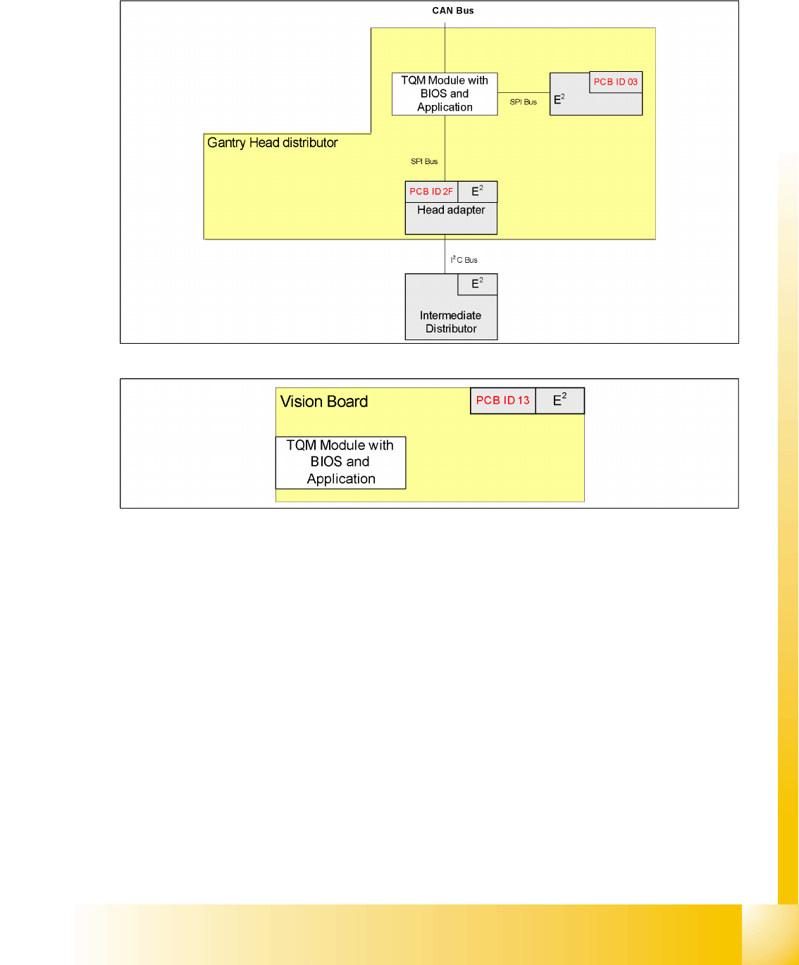
SIPLACE D series:
Gantry head distributor
Vision board
4.4 - 1: Overview of board IDs, checked by the TQM module (SIPLACE D)
4.4 - 2: Board IDs for Vision boards (SIPLACE D)
Communication and Control
Board type recognition What does it mean board type recognition?
Student Guide SIPLACE D4 (FSE)
Communication and Control EN 09/2006
96
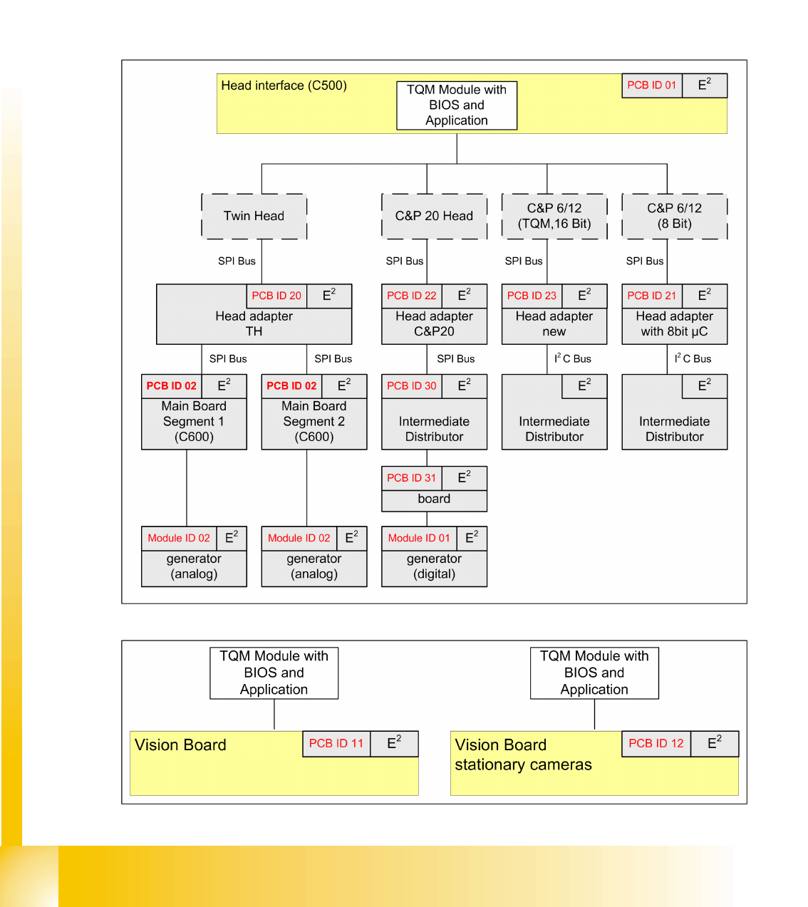
SIPLACE X series:
Head interface (Gantry 1-4)
Head adapter (C&P20, C&P6/12, Twin Head)
Intermediate distributor C&P 20
Main board Twin Head
Vision board (Gantry 1-4)
Illumination board stationary Cameras (Location 2/4)
Vacuumsensor holding circuit board C&P20
4.4 - 3: Overview of board IDs, checked by the TQM module (SIPLACE X)
4.4 - 4: Board IDs for Vision boards (SIPLACE X)
Communication and Control
Reading the Board IDs out of the EEPROM Board type recognition
Student Guide SIPLACE D4 (FSE)
EN 09/2006 Communication and Control
97
4.4.1.4 PCB‘s with board type ID‘s
4.4.2 Reading the Board IDs out of the EEPROM
The board ID can be checked with the help of the
Caccia
tool.
You can use CAN Bus commands to read the board type ID‘s or open the corresponding menue to read
the memory of the EEPROM. When one or more ID‘s are missing so you can write the correct ID on the
board.
At the moment it is necessary to use the correct ID‘s on the board which are installed on the gantry (Head
interface, - adapter, Intermediate distributor and main board). The other board type ID‘s are not used at
the moment.
NOTE:
At the moment, there is no check on the board type ID‘s from the vision boards
(gantry 1-4), illumination board stationary Cameras (Location 2/4) and the
Vacuumsensor holding circuit board C&P20.
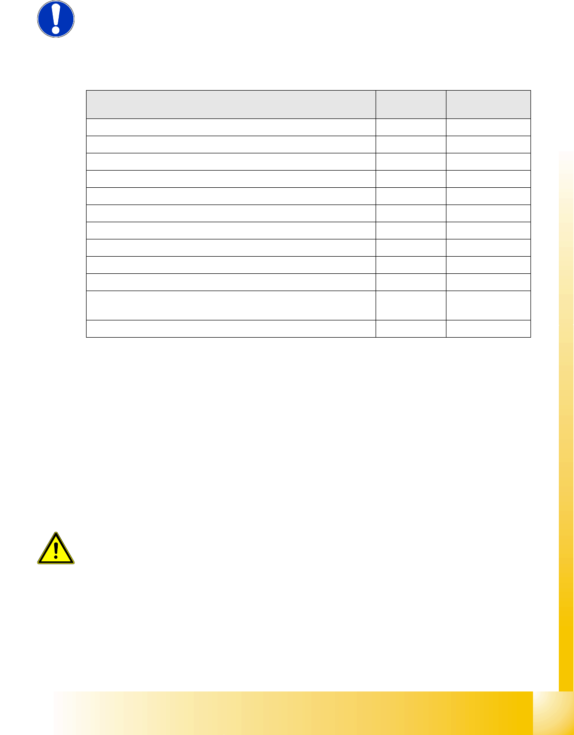
PCB‘s with ID Board ID Hardware version
of the PCB‘s
Head interface (C500) 0x01 -05
Head adapter C&P20 0x22 -04
Head adapter C&P6/12 (with 16 bit processor on the head interface) 0x23 -02
Head adapter C&P6/12 (with 8 bit processor on the head adapter) 0x21 -??
Head adapter Twin Head 0x20 -03
Intermediate distributor C&P 20 0x30 -06
Main board Twin Head (C600) 0x02 -08
Vision board 0x11 -??
Illumination board (stationary Cameras) 0x12 -??
Vacuumsensor holding circuit board C&P20 0x31 -02
Gantry head distributor SIPLACE D4 C&P12
Head adapter SIPLACE D4 C&P12
0x03
0x2F
-02
-02
Vision board SIPLACE D4 0x13 -01
ATTENTION:
Direct CAN bus commands should only be used by specially trained and
qualified service technicans.