00195193-02 SG D4 FSE en (1).pdf - 第99页
Communication and Control Board type recognition Reading the Board IDs out of the EEPROM S tudent Guide SIPLACE D4 (FSE) Communication and Control EN 09/2006 98 4.4.2.1 Read out the Board type ID via the menu Gripper X S…
Communication and Control
Reading the Board IDs out of the EEPROM Board type recognition
Student Guide SIPLACE D4 (FSE)
EN 09/2006 Communication and Control
97
4.4.1.4 PCB‘s with board type ID‘s
4.4.2 Reading the Board IDs out of the EEPROM
The board ID can be checked with the help of the
Caccia
tool.
You can use CAN Bus commands to read the board type ID‘s or open the corresponding menue to read
the memory of the EEPROM. When one or more ID‘s are missing so you can write the correct ID on the
board.
At the moment it is necessary to use the correct ID‘s on the board which are installed on the gantry (Head
interface, - adapter, Intermediate distributor and main board). The other board type ID‘s are not used at
the moment.
NOTE:
At the moment, there is no check on the board type ID‘s from the vision boards
(gantry 1-4), illumination board stationary Cameras (Location 2/4) and the
Vacuumsensor holding circuit board C&P20.
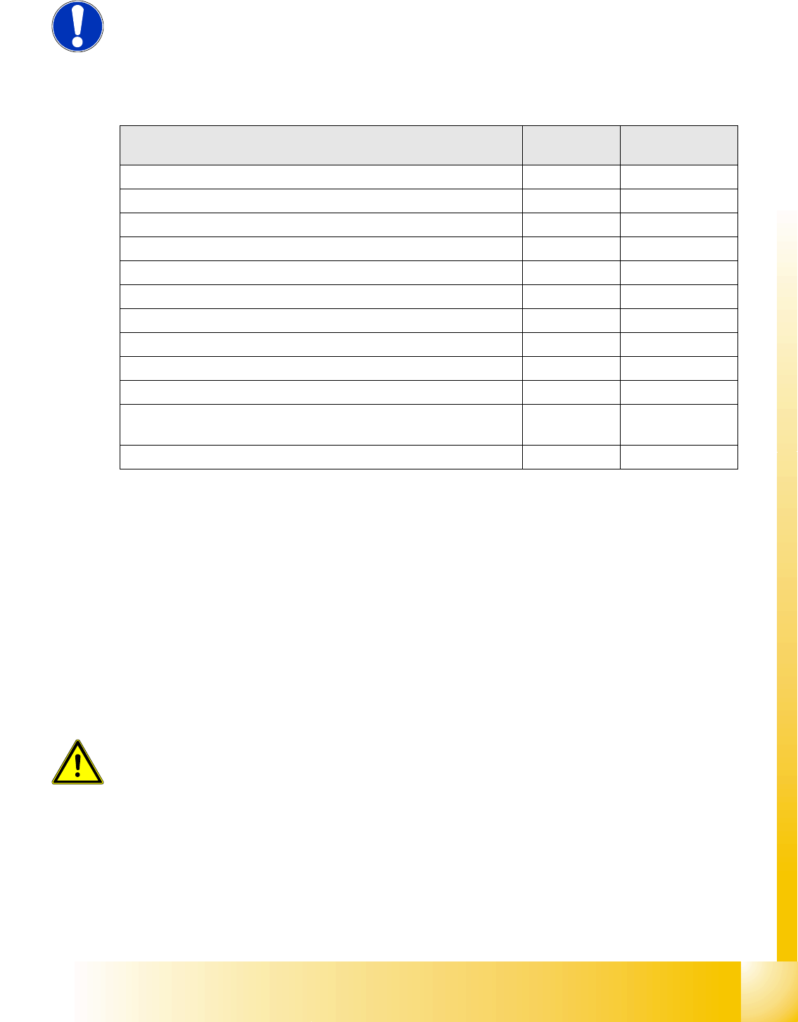
PCB‘s with ID Board ID Hardware version
of the PCB‘s
Head interface (C500) 0x01 -05
Head adapter C&P20 0x22 -04
Head adapter C&P6/12 (with 16 bit processor on the head interface) 0x23 -02
Head adapter C&P6/12 (with 8 bit processor on the head adapter) 0x21 -??
Head adapter Twin Head 0x20 -03
Intermediate distributor C&P 20 0x30 -06
Main board Twin Head (C600) 0x02 -08
Vision board 0x11 -??
Illumination board (stationary Cameras) 0x12 -??
Vacuumsensor holding circuit board C&P20 0x31 -02
Gantry head distributor SIPLACE D4 C&P12
Head adapter SIPLACE D4 C&P12
0x03
0x2F
-02
-02
Vision board SIPLACE D4 0x13 -01
ATTENTION:
Direct CAN bus commands should only be used by specially trained and
qualified service technicans.
Communication and Control
Board type recognition Reading the Board IDs out of the EEPROM
Student Guide SIPLACE D4 (FSE)
Communication and Control EN 09/2006
98
4.4.2.1 Read out the Board type ID via the menu Gripper
X Switch off the machine.
X Connect the service laptop to the machine CAN bus at PA1 and/or PA2.
Make sure that the cable to channel 1 is connected to PA 1 and that the transceiver is connected to
channel 2 of the Kvaser Card or switch off the query for the transceiver at channel 2 in the
Advanced
Subsystem Configuration
menu.
X Switch on the machine
X Start the
Caccia
software and check the machine configuration in
Caccia
.
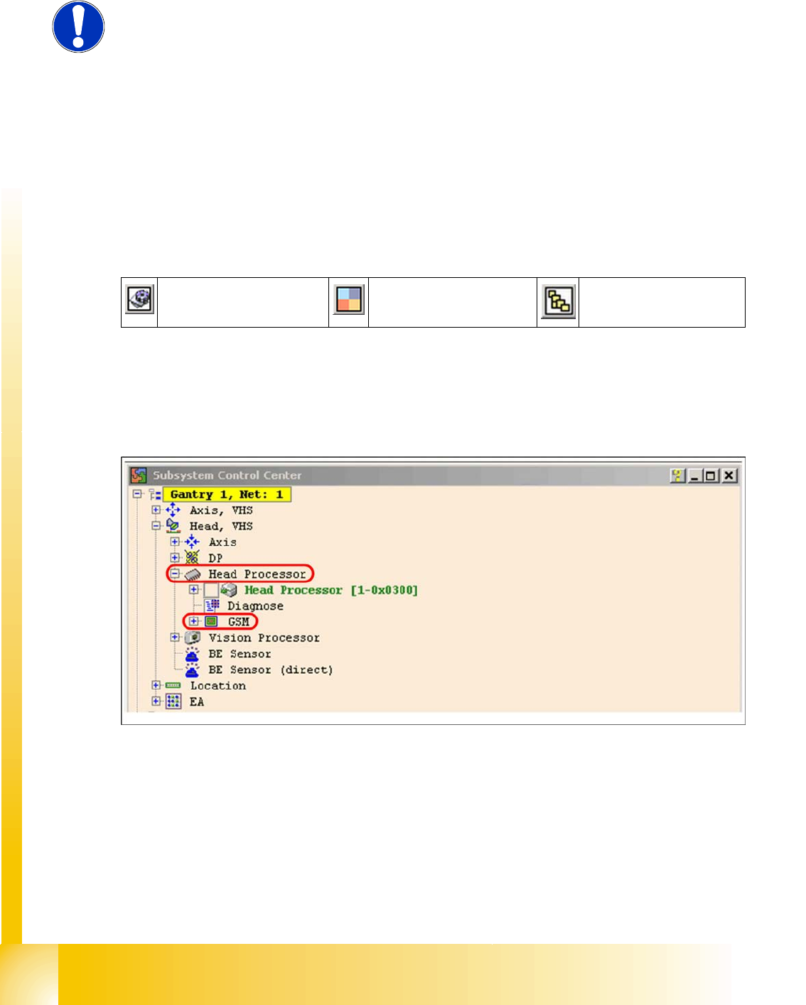
X This can be opened by double-clicking on the
Subsystem control center
Press on the
Get Versions
button . All available subsystems will be shown with their firmware versions
and their CAN IDs.
X Choose the head processor according the gantry e.g. gantry 1
X Open the
GSM
folder.
4.4 - 5: Subsystem control center
X Double-click on
Gripper
and the following dialog box will open:
NOTE:
When you want to be read out the board type ID‘s via the menu gripper, the
BIOS and application-software have to downloaded on the TQM module.
Reading out is currently only possible via the
Gripper
menu. to write the ID‘s
on the EEPROM you need CAN Bus commands.
Subsystem control center Machine configuration
window
Advanced
Subsystem Configuration
Communication and Control
Reading the Board IDs out of the EEPROM Board type recognition
Student Guide SIPLACE D4 (FSE)
EN 09/2006 Communication and Control
99
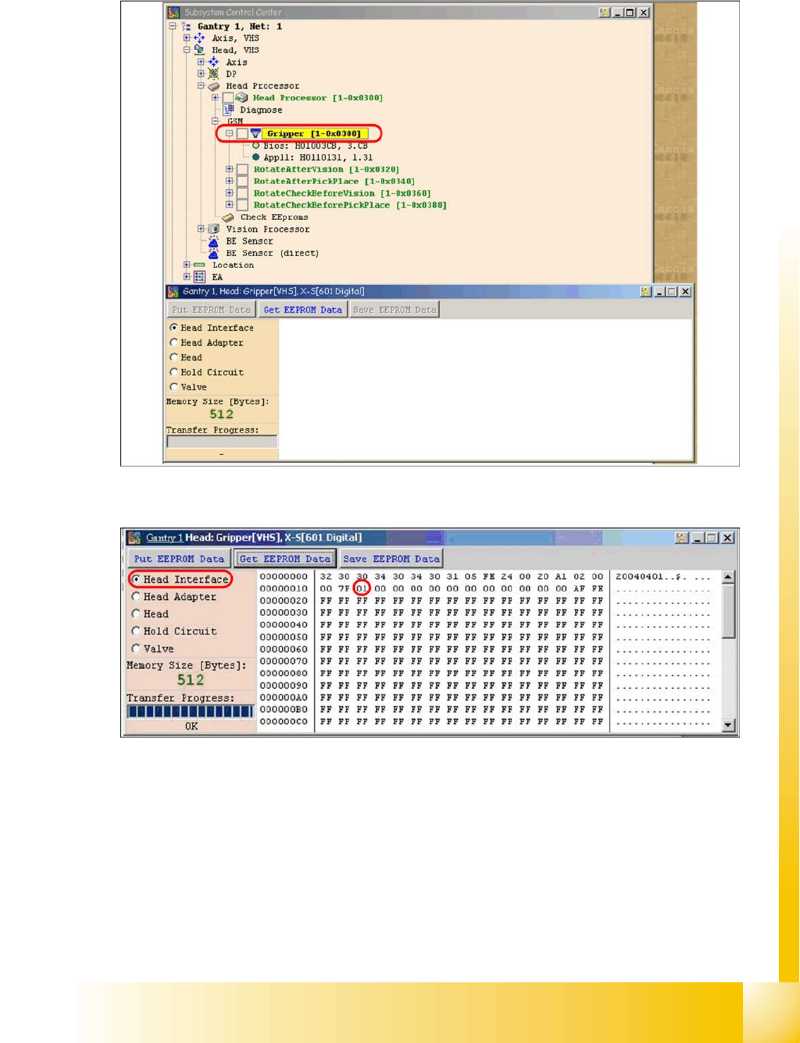
4.4 - 6: Dialog head processor gripper
X Select the board to be
checked
and click on the
Get EEPROM button.
4.4 - 7: Head interface board type recognition ID 01
X The ID will appear in the
memory cell
12, the ID 01 for the head interface C500.