What is New in IPC-7351C.pdf - 第22页
PC B L ibr ar i es Pr e s ents : Wh at is N ew i n IPC- 7351C Com po ne nt Body & T e r m ina l Outline s • Th e N ominal C ompon e nt Bod y and T e r m i nal Le ad Outl in e s • Outp ut to CAD too l o n a me c hani …
PCB Libraries Presents:
What is New in IPC-7351C
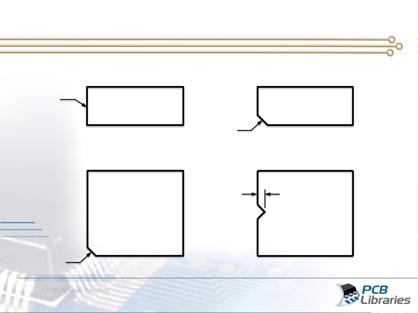
Assembly Outline & Polarity Guidelines
Non-polarized Chip,
Crystal, Molded Body
Polarized Chip, SOD,
LED, SOT. Molded Body
Plastic Leaded Chip Carrier
PLCC, LCC, 4-sided Chip Array
Small Outline Package
SOP, SON, QFN, QFP
1.00 mm
1.00 mm
1.00 mm
0.10 mm
Line Width
PCB Libraries Presents:
What is New in IPC-7351C
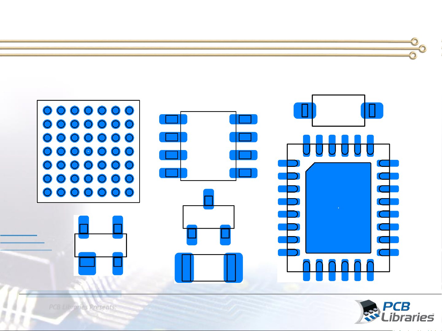
Component Body & Terminal Outlines
• The Nominal Component Body and Terminal Lead Outlines
• Output to CAD tool on a mechanical layer
PCB Libraries Presents:
What is New in IPC-7351C
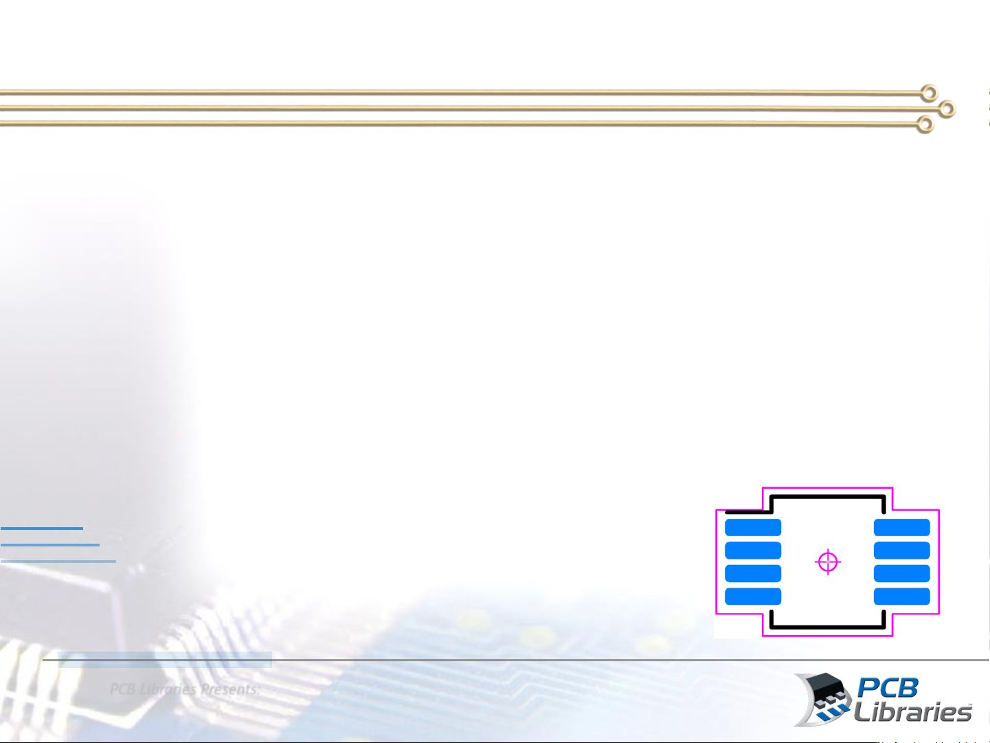
3-Tier Silkscreen Reference Designators
• Silkscreen reference designators are normally placed inside the
courtyard during library construction and typically located on the
land pattern origin. After part placement has been approved, the
silkscreen ref des are relocated outside the component body so
they are visible after assembly.
• The ref des line width is normally 10% of the text height
• In the past, we made all silkscreen reference designators 1.50 mm
height. Fabrication technology has improved it’s time to support a
3-Tier reference designator option
• New recommendations for the 3-Tier ref des
– Least Density Level: 1.00 mm Height
– Nominal Density Level: 1.20 mm Height
– Most Density Level: 1.50 mm Height
REFDES