What is New in IPC-7351C.pdf - 第41页
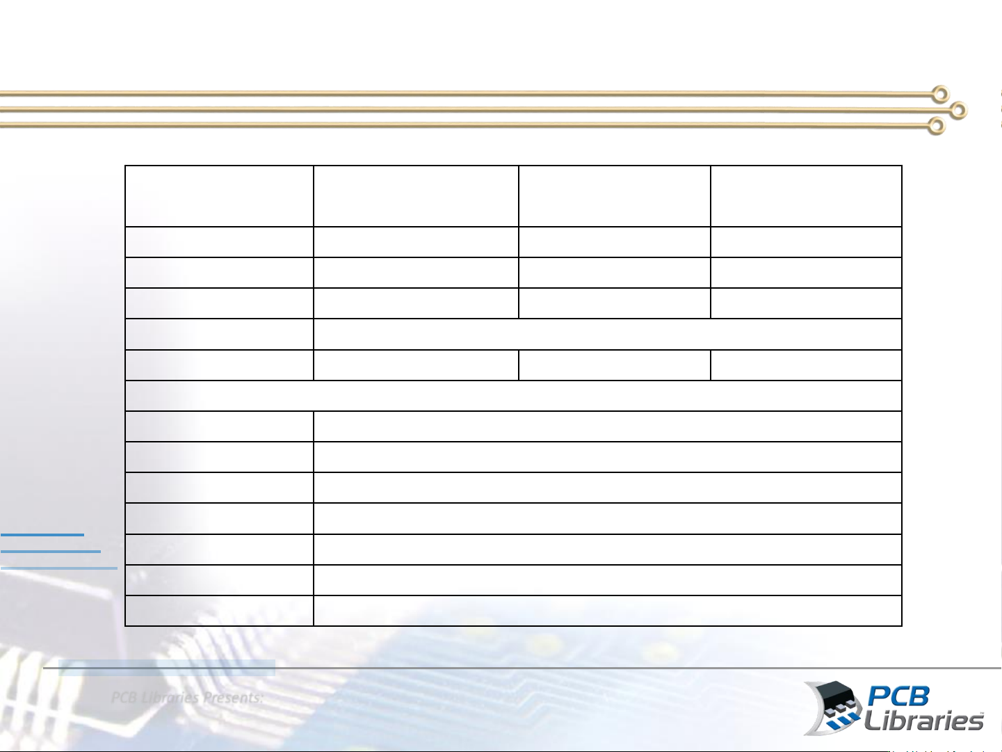
PC B L ibr ar i es Pr e s ents : Wh at is N ew i n IPC- 7351C N ew S old e r Join t G oa l R ecom mend a t i on s Propo rt iona l SM D Pad St ack 5 0% He ight 1 0% He i gh t 1 5% He i gh t Pa cka ge Dimens ion s 4 0% He …
PCB Libraries Presents:
What is New in IPC-7351C
Lead Part
Maximum (Most)
Density Level A
Median (Nominal)
Density Level B
Minimum (Least)
Density Level C
Toe
(J
T
) 0.55 0.35 0.15
Heel
(J
H
) 0.00 0.00 0.00
Side
(J
S
) 0.05 0.00 -0.05
Round
-off factor
Round
off to nearest two place decimal, i.e., 1.00, 1.01, 1.02
Courtyard
excess 0.50 0.25 0.12
Rectangular Chip Components Smaller than 1608 (0603) (unit: mm)
Toe
(J
T
) 0402 0.15
Toe
(J
T
) 0201 0.12
Toe
(J
T
) 01005 0.10
Heel
(J
H
) 0.00
Side
(J
S
) 0.00
Round
-off factor
Round
off to nearest two place decimal, i.e., 1.00, 1.01, 1.02
Courtyard
excess 0.15
Solder Joint Goals for Chip Components < 0603
PCB Libraries Presents:
What is New in IPC-7351C
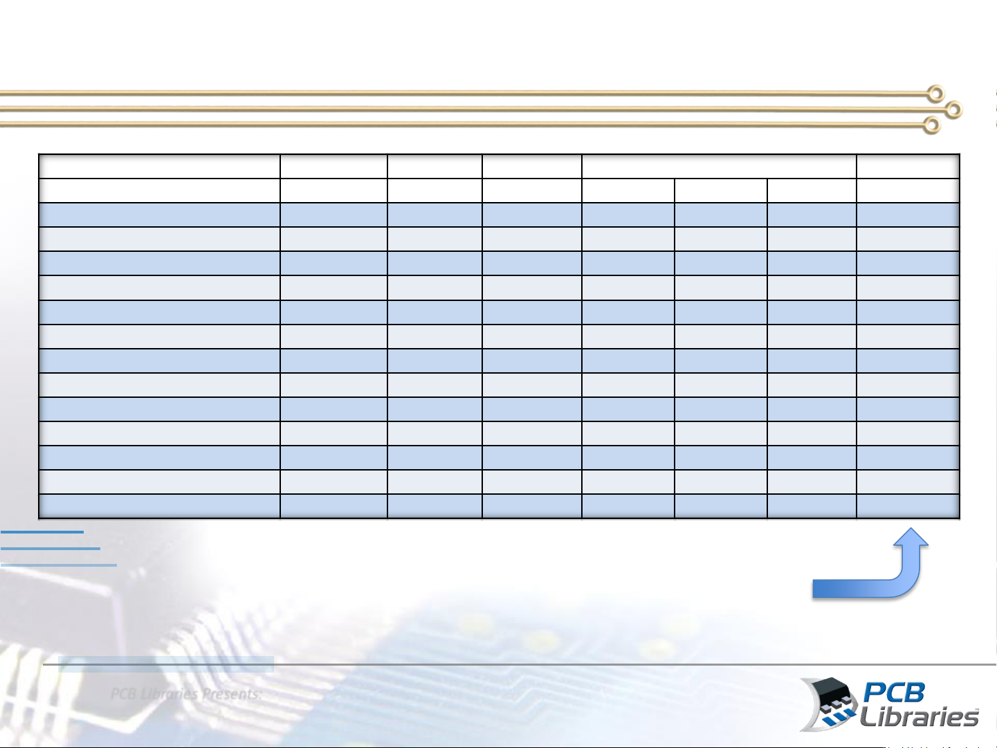
New Solder Joint Goal Recommendations
Proportional SMD Pad Stack
50% Height
10% Height
15% Height
Package Dimensions
40% Height
Rectangular
End Cap Toe Heel Side Length Width Height
Courtyard
Inch
01005, Metric 0402
0.075 0.015 0.023
0.40 mm
0.20 mm
0.25 mm
0.10
Inch
0201, Metric 0603
0.150 0.030 0.045
0.60 mm
0.30 mm
0.30 mm
0.12
Inch
0402, Metric 1005
0.185 0.037 0.056
1.00 mm
0.50 mm
0.40 mm
0.16
Inch
0603, Metric 1608
0.275 0.055 0.083
1.60 mm
0.80 mm
0.50 mm
0.20
Inch
0805, Metric 2012
0.300 0.060 0.090
2.00 mm
1.25 mm
0.60 mm
0.24
Inch
1008, Metric 2520
0.325 0.065 0.098
2.50 mm
2.00 mm
0.65 mm
0.25
Inch
1206, Metric 3216
0.350 0.070 0.105
3.20 mm
1.60 mm
0.70 mm
0.25
Inch
1210, Metric 3225
0.350 0.070 0.105
3.20 mm
2.50 mm
0.70 mm
0.25
Inch
1806, Metric 4516
0.375 0.075 0.113
4.50 mm
1.60 mm
0.75 mm
0.25
Inch
1812, Metric 4532
0.400 0.080 0.120
4.50 mm
3.20 mm
0.80 mm
0.25
Inch
2010 , Metric 5025
0.400 0.080 0.120
5.00 mm
2.50 mm
0.80 mm
0.25
Inch
2512, Metric 6332
0.400 0.080 0.120
6.40 mm
3.20 mm
0.80 mm
0.25
Inch
2920, Metric 7451
0.400 0.080 0.120
7.40 mm
5.10 mm
0.80 mm
0.25
Limit Maximum Courtyard setting to
0.25 mm but make it User Definable
PCB Libraries Presents:
What is New in IPC-7351C
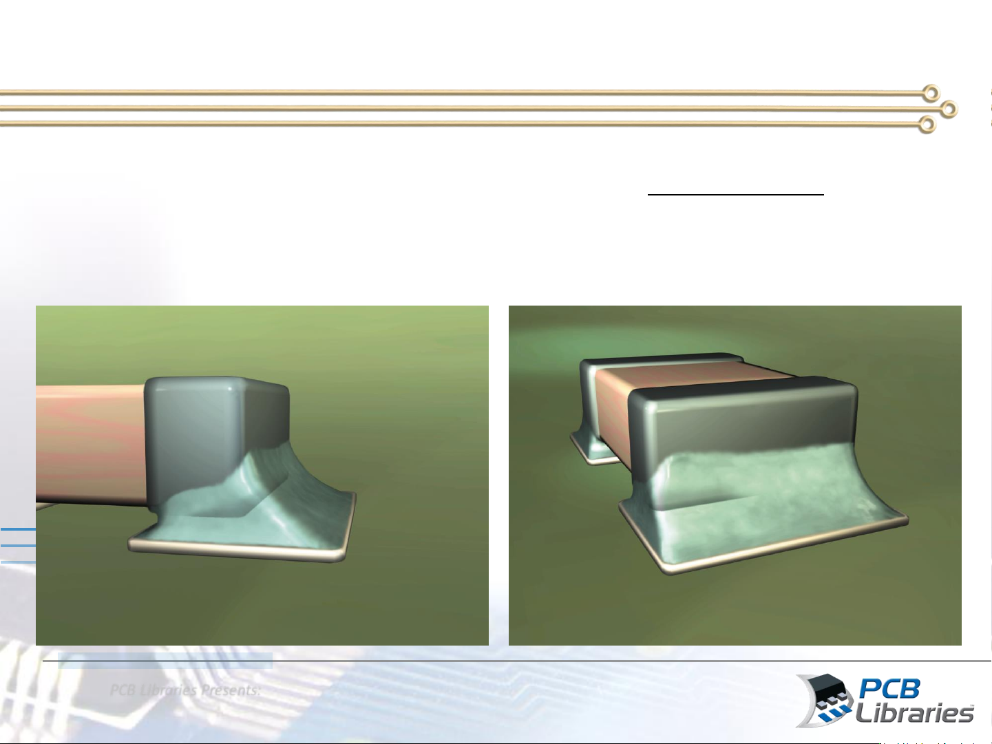
J-STD-001 Chip Component Solder Joints
• Visible Wetting Evident on the vertical surfaces of the component termination
• Minimum End Solder Fillet 25% of Height or 0.50 mm Whichever is Less – Class 3
• Minimum End Solder to be 75% of the Length. The Pad Width is Critical – Class 3
• The Side and Heel are Nominal Values But Must Insure Centering
• The Pad Spacing Center to Center is Critical To Avoid Excess Heel