5OM-1075-002.pdf - 第103页
Section 5 Code Connection Diagrams Connection Diagram of Motor Relay Board 0308-001 A(M750JVE--2102) 5-2 AHB01EMTP -XCN8 CN1 CN3 XCN63A XCN63 NC1 NC2 TV2 TV1 CN12 (UA85) (UA85) CN11 CVR PWC CVP CVL XCN62 XCN62A CN2 CN1 C…
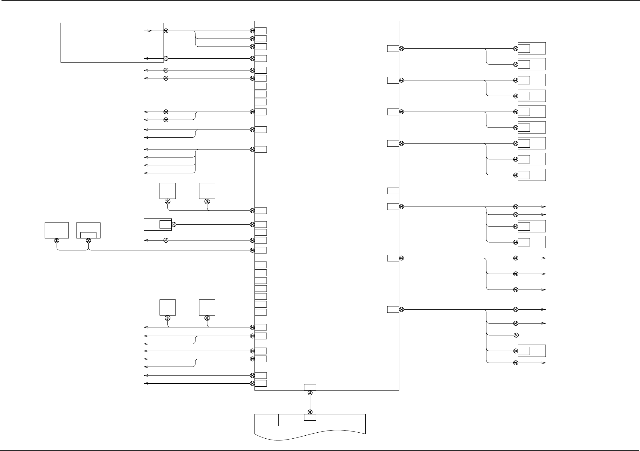
Section 5 Code Connection Diagrams
External Connection Diagram of I/O Relay P.C.B.
0308-001 C(M750JVE--2101) 5-1 AHB01EMTP
XCN205A XCN205
X505R
-XCN8
XCN26A
XCN1-F3
XCN1-Q3
XCN1-Q2
-XCN1-N
XCN1-F4
-XCN1-N
XCN1-Q4
XCN1-Q1
XCN1-B
XCN49
CN49
XCN47
XCN48
CN48
CN47
CN45
CN46
XCN45
CN43
CN42
CN40
CN41
CN37
CN38
CN35
UA75
UA60
XCN33
CN33
CN31
CN32
XCN32
XCN30A
CN1
XCN30
CN30
XCN28
CN28
CN29
XCN27
CN27
CN26
XCN26
XCN25
CN25
TV2 (IO)
XCN1-TV2
XCN2-TV2
TV2 (OP)
CN24
CN23
CN22
XCN21XCN3A-VC
CN21
PANEL-A
PANEL-A
XCN3B-VC
PANEL-B
PANEL-B
CN20
XCN20630 102 3922
(24B19,10B) XCN53
CN53
CN52
XCN52(24B10,10B)
(6E1,10E) XCN51
CN51
XCN61
XCN11
(IOMB)
(MCMB)
CN1
CN11
UA93
MCMB
NSTK (B1)
FB3
CVR
XCN19
CN19
XCN01X1
HEAD1
NSTK (B2)
CVL
HEAD2
XCN01X2
CN18
XCN18
FB4
FB1
XCN1-PXCN17
CN17
CN16
XCN1-BPC
ASMD-BPC
CN1
XCN15 XCN1-L2
ASMD-L2
CN15 CN1
CN1
ASMD-Z2
XCN1-Z2
XCN1-Z1
ASMD-Z1
CN1
CN1CN14
ASMD-L1
XCN1-L1XCN14
XCN13 XCN1-X2
ASMD-X2
CN13 CN1
CN1
ASMD-Y2
XCN1-Y2
XCN1-Y1
ASMD-Y1
CN1
CN1CN12
UA92
CVP
ASMD-X1
XCN1-X1XCN12
PIO
CN2
CN2
CN2
630 102 3939
630 102 3946
630 102 3953
CN44
630 095 2094
XCN46
630 099 5985
630 099 5992
630 099 6005
630 099 6012
630 102 3892
630 102 3908
630 102 3915
VE S-258
XCN44
NC1 NC2
NC2NC1
XCN29
(+5V,+24V,S24V)
FB2
XCN5-NC2XCN5-NC1
XCN1-NC1 XCN1-NC2
Relay Board (UA96)
Brake Control Relay
Lightning Surge (Q201)
Y1-Axis Limit (+)
Y1-Axis Limit (-)
Y2-Axis Limit (+)
Y2-Axis Limit (-)
Lighting Control
Board
Recognition
Board
VGA Distributor
To Tray 2
BPC Base Lower Limit Detection Sensor
X1-Axis Limit (+)
Beam Synchronous Deviation Detection Sensor
X2-Axis Limit (-)
Mispicked Component Detection A
Mispicked Component Detection B
Component Storage Box A Full Detection
Component Storage Box B Full Detection
Note 1
Note 1
Note 1: The component storage box full detection sensor
will be mounted on either Side A or B.
Y-Axis Limit Sensor
Power Input 5 V
24 V for Power Input Sensor
24 V for Power Input
Solenoid Valve
Signal from
Relay Board
Carriage Cart (2.3) Right
Carriage Cart (1.4) Left
Traverse 1 (Option)
Traverse 2 (Option)
Brake Relay/Lightning Surge
Vertical Bend (Option)/
NC-Axis Boost Current
Component Storage
Box B Full Detection
Component Storage
Box A Full Detection
I/O Relay Board
Mispicked Component
Detection Sensor (BPH071, 072)
X2-Axis Limit (+)/Beam Synchronous
Deviation Detection Sensor 2 (Reserved)
X1-Axis Limit (+)/Beam Synchronous
Deviation Detection Sensor 1
NC-Axis Current Value Selection/
BPC Base Lower Limit Detection Sensor
Cycle Conveyor B (Option)
Cycle Conveyor A (Option)
Nozzle Stocker A2 (Option)
Nozzle Stocker A1 (Option)
Reserved
Reserved
Safety Bar (Reserved)
Image Capture Trigger
Tray 2 Interlock
Tray 1 Interlock
Manifold (Transfer)
Driver (X1, Y1)
Driver (X2,Y2)
Driver (L1,Z1)
Driver (L2,Z2,BPC)
Vertical Bend (Option)
Mechanical Equipment
Left Side 1
Mechanical Equipment
Left Side 2
Mechanical Equipment
Right Side
(Option)
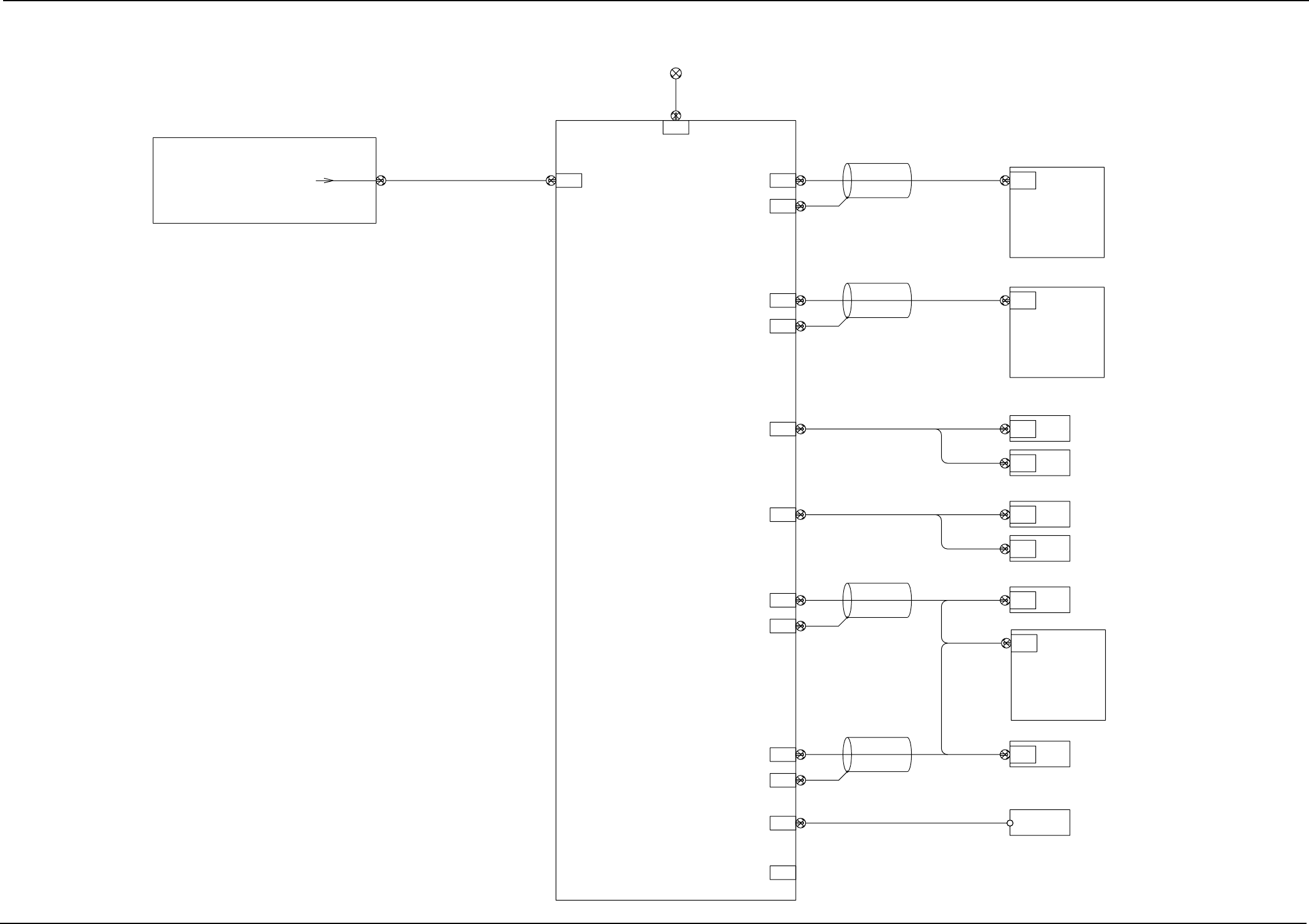
Section 5 Code Connection Diagrams
Connection Diagram of Motor Relay Board
0308-001 A(M750JVE--2102) 5-2 AHB01EMTP
-XCN8
CN1CN3
XCN63AXCN63
NC1
NC2
TV2
TV1
CN12
(UA85)
(UA85)
CN11
CVR
PWC
CVP
CVL
XCN62 XCN62A
CN2 CN1
CN14
CN13
CN8
APMD-PWC
XCN68
XCN67 XCN1-NC2
APMD-NC2
CN7 CN1
CN1CN6
APMD-NC1
XCN1-NC1XCN66
ASMD-TV2
XCN1-TV2
CN1
XCN65 XCN1-CVR
ASMD-CVR
CN5 CN1
XCN1-CVP
ASMD-CVP
CN1
CN1CN4
ASMD-CVL
XCN1-CVLXCN64
(24B5,10B)
CN10
(+24V)
XCN61
XCN11
(IOMB)
CN1
HLS
MCB1
-XCN70
630 099 5909
630 099 5916
630 099 5923
630 099 5961
630 099 5978
630 099 5930
630 099 5954
HLS
MCB2
CN9
XCN29
(UA92)
CN29
Relay Board (UA96)
HLS MCB1 (UA85)
HLS MCB2 (UA85)
Motor Relay Board
UA93
Driver (CVL, CVP)
Driver (CVR, TV2)
Shielded
Power Supply
Relay Board
To UA92
Driver (NC1)
Driver (NC2)
Driver (PWC)
Driver (TV1)
(Option)
Shielded
Shielded
Shielded
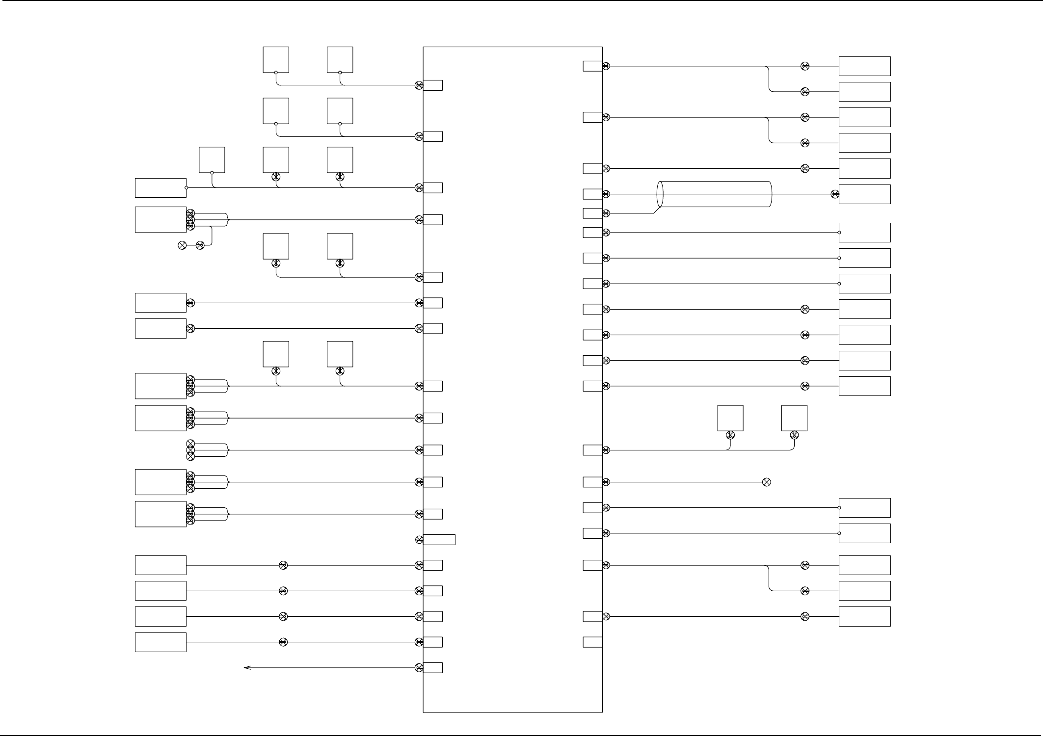
Section 5 Code Connection Diagrams
Connection Diagram of Relay Board
0308-001 B(M750JVE--2103) 5-3 AHB01EMTP
-XCN40
CN40
CN39
-XCN39
-XCN38
CN38
(K25)
(K15)
SP1
CN37
-XCN37
CN36
-XCN36
CN35
MCB2MCB1
-XCN34
CN34
UA85
CN2 CN2
UA85
-XCN32
CN32
CN33
-XCN33
-XCN30
CN30
CN31
-XCN31
-XCN29
CN29
CN28
-XCN28
-XCN27
CN27
CN26
UA92
XCN26A
CN26
CN25
-XCN25
CN24
XCN24
G1 G3
G5G2
G2
G4 G5
NC1 NC2
LCDA
UA75
CN1
CN21
-XCN21
-XCN22
CN22
CN20
-XCN20
-XCN19
CN19
CN13to18
CN22
CN5
CN20
CN11
-XCN11
UA76-03
UA76-03
-XCN12
CN12
CN20
CN5
CN22
CN10
-XCN10
UA76-03
-XCN9
CN9
CN20
CN5
CN22
CN10
UA93
UA92
-XCN8
CN8
CN52
CN51
CN53
LCDB
-XCN7
CN7
CN6
-XCN6
-XCN5
CN5
CN4
CN1
CN2
CN4
-XCN4
UA53
-XCN3
CN3
-XCN2
CN2
XCN23
UA96
CN23
CN1
-XCN1
(24A)
(24B)
(24C)
(6E)
(CN24CA)
(CN24B6E)
(CNVME)
(CNUA53)
(CNNC)
(CNLCDA)
(CNLCDB)
(CNUA)
(CNFB1)
(CNFB2)
(CNFB3)
(CNFB4)
CN42
(CNFAN1)
(CNFAN2)
(CNFAN3)
(CNFAN4)
XCN26
(CNPNLA)
(CNPNLB)
(CNSP1)
(CNRDR)
(CNLDR)
(CNQKM)
(CNSQ1)
(CNSQ2)
(CNMNTL)
(CNMNTR)
(CNMCB)
(CNTRY2)
(CNSRLY1)
(CNSRLY2)
(CNTWRP)
(CNPART)
XCN164 XCN165
630 102 3953
630 099 2182
(CNSPRP)
CN41
-XCN41
Power Supply for
Rear Left Boards in Frame
Feeder Base #1 Power Supply
(Option)
Fan Motor 2 in Frame
Operation Panel A/
Emergency Stop (Front Left)
Operation Panel B/
Emergency Stop (Rear Right)
Front Left Door KM/CP
Safety Door Switch on
Side B
Right Detection Sensor in
Maintenance Opening Section
Safety Relay 1 (K25)
Tray 1 Power Supply
(Option)
Light Tower/
Component Shortage Lamp A
Component Shortage Lamp B
Emergency Stop
(Rear Right)
Power Panel
Maintenance Opening
Detection (Left)
Maintenance Opening
Detection (Right)
Safety Relay 2
Safety Relay 1
Light Tower
Component Shortage
Lamp A
Component Shortage
Lamp B
XCN241
XCN242
XCN244
XCN231
XCN221
XCN51
XCN52
XCN53
XCN5-Q1
XCN20-Q1
XCN22-Q1
XCN22-Q2
XCN20-Q2
XCN5-Q2
XCN22-Q3
XCN20-Q3
XCN5-Q3
XCN22-Q4
XCN20-Q4
XCN5-Q4
XCN1-NC1 XCN1-NC2
KM-NC
VME Rack
(I/O Relay)
Feeder Base #1
Feeder Base #3
Feeder Base #4
(M Relay)
(Lighting)
Fan Motor
Fan Motor
Fan Motor
Fan Motor
Input & Output Machines/
Safety Circuit Power Input
IO 24V/HLS 5V Power Input
VME Rack/Power Remote
Front and Rear Interface Board
(UA53) Power Supply
NC-Axis Motor Driver
Control Power Supply
LCD Panel A Power Supply
LCD Panel B Power Supply
Feeder Base #2 Power Supply
(Option)
Feeder Base #3 Power Supply
Feeder Base #4 Power Supply
Fan Motor 1 in Frame
Fan Motor Cover 1
Fan Motor Cover 2
NC-Axis Driving Power Supply
Pressure Sensor
I/O Relay Signal Wire
Front Right Door KM/CP
Power Panel KM/CP
Safety Door Switch on
Side A
Left Detection Sensor in
Maintenance Opening Section
HLSMCB Power Supply
Tray 2 Power Supply
Safety Relay 1 (K15)
Panel A
Emergency Stop
(Front Left)
Panel B
Pressure Sensor
Front Right Door
Front Left Door
Safety Door
Switch (A)
Safety Door
Switch (B)
Relay Board
Tray 2