00198761-01_SM_Head_Care_Station_II_EN - 第29页
4 Service work – HCSII Head Unit 4.6 Replacing the Base Adapter C&P / MHCU Service Manual SIPLACE Head Care Station II 11/2019 29 4.6 Replacing the Base Adapter C&P / MHCU Parts Fig.27: PCB Base Adapter C&P…
4 Service work – HCSII Head Unit
4.5 Replacing the Board Adapter LP Twin
28 Service Manual SIPLACE Head Care Station II 11/2019
4.5 Replacing the Board Adapter LP Twin
Parts
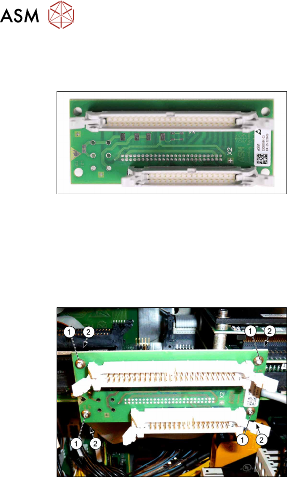
Fig.25: Board Adapter-LP Twin-HCSII
●
Board Adapter-LP Twin-HCSII
[03087844‑xx]
Preparatory work...
► Turn off and disconnect the HCS II. See 3.1 "Turn off and disconnect the HCS II" [}19].
► Perform the steps described in section 3.3 "Access to the spare parts of the HCS II Head
Unit" [}20].
Removal
Fig.26: Removal
► Unplug the flat ribbon cables.
► Remove the four screws(1) fastening
the Board Adapter LP Twin on the
Base Adapter-Twin.
► Hold the screw nuts(2) from behind
(e.g. with tweezers).
► Make sure that the screws and screw
nuts are not lost.
Installation
► Follow the removal instructions in reverse order for installation.
► Replace any cable ties which you have removed.
4 Service work – HCSII Head Unit
4.6 Replacing the Base Adapter C&P / MHCU
Service Manual SIPLACE Head Care Station II 11/2019 29
4.6 Replacing the Base Adapter C&P / MHCU
Parts
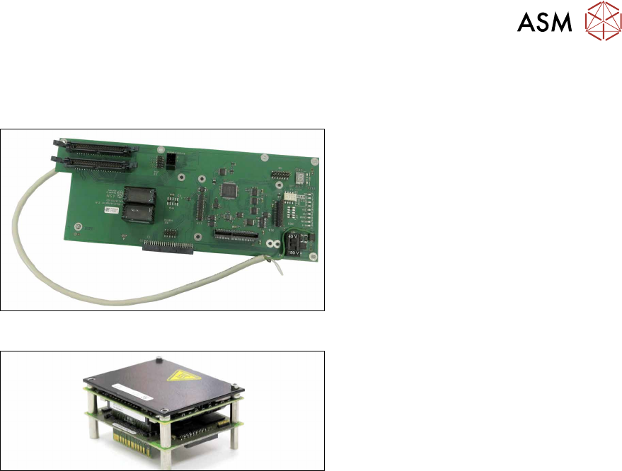
Fig.27: PCB Base Adapter C&P HCS2.3
●
PCB Base Adapter C&P HCS2.3
[03158917‑xx]
Fig.28: MHCU complete compatible
●
MHCU complete compatible
[03090990‑xx]
Preparatory work...
► Turn off and disconnect the HCS II. See 3.1 "Turn off and disconnect the HCS II" [}19].
► Perform the steps described in section 3.3 "Access to the spare parts of the HCS II Head
Unit" [}20].
► Remove the compressed air filter. See 4.2 "Replacing the compressed air filter" [}24].
4 Service work – HCSII Head Unit
4.6 Replacing the Base Adapter C&P / MHCU
30 Service Manual SIPLACE Head Care Station II 11/2019
Removal
► Open any cable ties where necessary. You may want to mark the positions of the relevant
connections to make clear assignment easier later on.
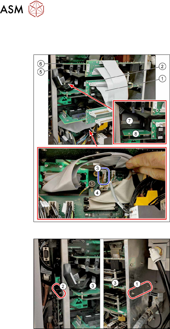
Fig.29: Removal 1
► Unplug the two flat ribbon cables(1)
from the Board adapter(2).
► Unplug the round cable X90(3) from
the Board Adapter Head Interface(4)
(main PCB at the back side).
► Unplug the black cable X5(5) from the
Modul Head Interface(6).
(Unlock the plug by pressing both
sides.)
► Unplug the two flat ribbon cables X1/
X2(7) from the Base Adapter(8).
(The plugs are locked on both sides.)
Fig.30: Removal 2
► Remove the two screws(1) fastening
the Base Adapter C&P(3) assembly
bracket on the right side.
Make sure that the screws are not lost.
► Loosen the two screws(2) (keyholes,
do not remove the screws!) fastening
the Base Adapter C&P(3) assembly
bracket on the left side.