00198761-01_SM_Head_Care_Station_II_EN - 第36页
4 Service work – HCSII Head Unit 4.10 Replacing the Vision Board 36 Service Manual SIPLACE Head Care Station II 11/2019 4.10 Replacing the Vision Board Parts Fig.43: Vision Board Spread Spectrum HCU ● Vision Board Spre…
4 Service work – HCSII Head Unit
4.9 Replacing the Board Adapter LP C700B
Service Manual SIPLACE Head Care Station II 11/2019 35
4.9 Replacing the Board Adapter LP C700B
Parts
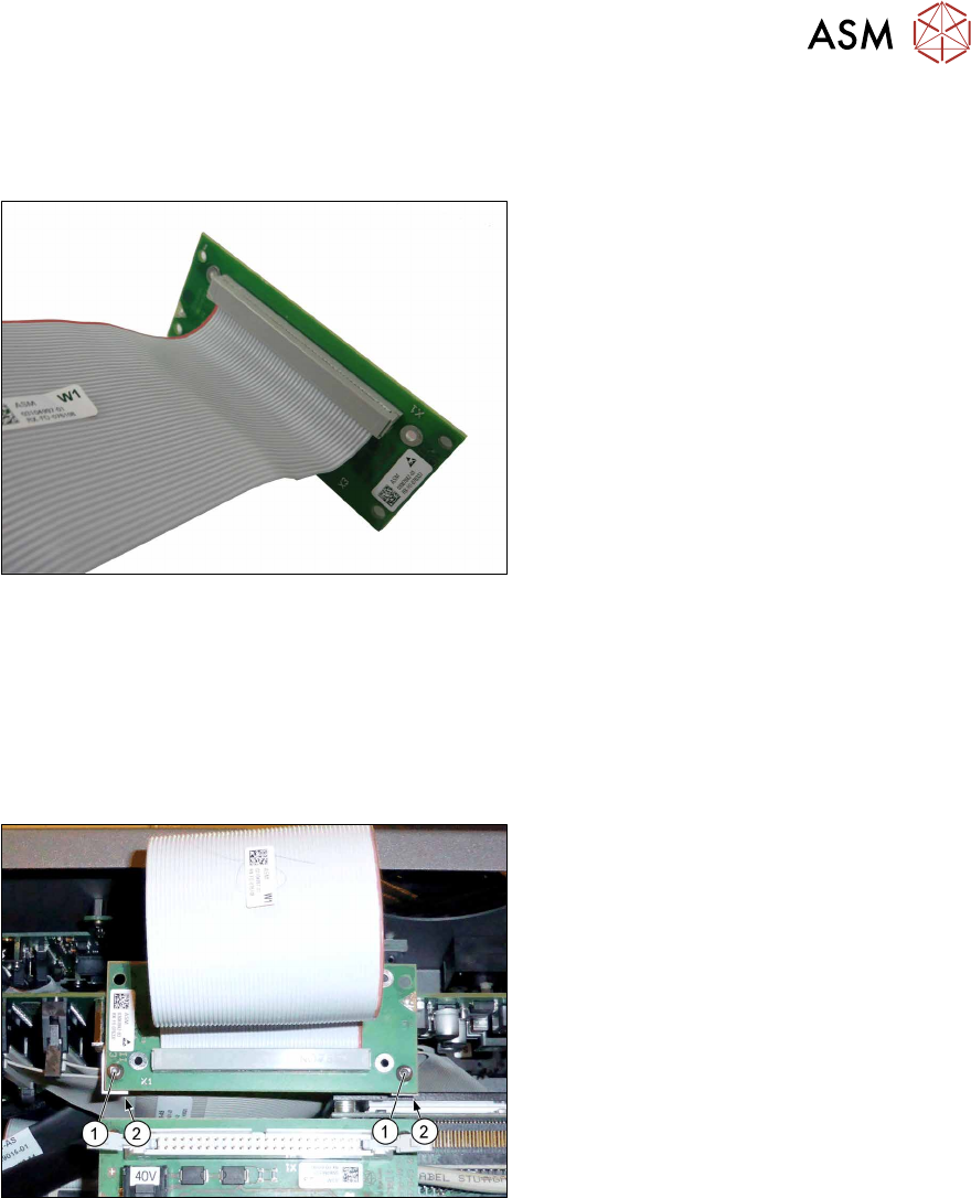
Fig.41: Board Adapter LP C700B HCSII
●
Board Adapter LP C700B HCSII
[03087842‑xx]
Preparatory work...
► Turn off and disconnect the HCS II. See 3.1 "Turn off and disconnect the HCS II" [}19].
► Perform the steps described in section 3.3 "Access to the spare parts of the HCS II Head
Unit" [}20].
Removal
Fig.42: Removal
► Unplug the flat ribbon cables.
► Remove the two screws(1) fastening
the Board Adapter LP C700B on the
Modul Head Interface C700B.
► Hold the screw nuts(2) from behind
(e.g.with tweezers).
► Make sure that the screws and screw
nuts are not lost.
Installation
► Follow the removal instructions in reverse order for installation.
► Replace any cable ties which you have removed.
4 Service work – HCSII Head Unit
4.10 Replacing the Vision Board
36 Service Manual SIPLACE Head Care Station II 11/2019
4.10 Replacing the Vision Board
Parts
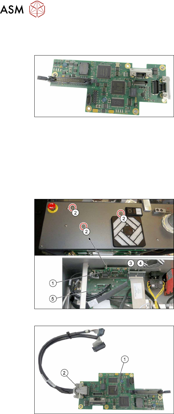
Fig.43: Vision Board Spread Spectrum HCU
●
Vision Board Spread Spectrum HCU
complete [03067289‑xx]
Preparatory work...
► Turn off and disconnect the HCS II. See 3.1 "Turn off and disconnect the HCS II" [}19].
► Perform the steps described in section 3.3 "Access to the spare parts of the HCS II Head
Unit" [}20].
► Remove the Modul Head Interface-C700B. See 4.8 "Replacing the Head Interface-
C700B" [}34].
Removal
Fig.44: Removal
► Open any cable ties where necessary.
You may want to mark the positions of
the relevant connections to make clear
assignment easier later on.
► Unplug the cable J7/X7(3).
► Unplug the flat ribbon cable X4.A4(4).
► Unplug the two round cables W1/
W2(5) from the Board Adapter Head
Interface.
► Remove the tree small screws(2)
fastening the Vision Board(1) on the
frame. Make sure that the screws are
not lost.
► Carefully remove the Vision Board.
Fig.45: Vision Board Spread Spectrum HCU
1. Vision Board Spread Spectrum HCU
complete [03067289‑xx]
2. Cables W1/W2
► Remove the cables W1/W2(2) from the
Vision Board(1).
Installation
► Follow the removal instructions in reverse order for installation.
► Replace any cable ties which you have removed.
4 Service work – HCSII Head Unit
4.11 Replacing the Assembly PCB digital
Service Manual SIPLACE Head Care Station II 11/2019 37
4.11 Replacing the Assembly PCB digital
Parts
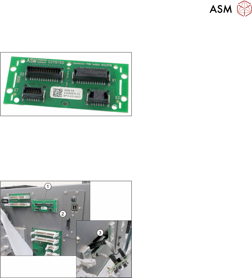
Fig.46: Assembly PCB digital
●
Assembly PCB digital [03008825‑xx]
Preparatory work...
► Turn off and disconnect the HCS II. See 3.1 "Turn off and disconnect the HCS II" [}19].
► Perform the steps described in section 3.3 "Access to the spare parts of the HCS II Head
Unit" [}20].
Removal
Fig.47: Removal
► Remove the four screws(2) fastening
the Assembly PCB digital(1) on the
frame.
► Pull the PCB forward(3) out of the
frame.
► Unplug the cables.
Installation
► Follow the removal instructions in reverse order for installation.
► Replace any cable ties which you have removed.