00198761-01_SM_Head_Care_Station_II_EN - 第60页
5 Service work – HCSII Control Box 5.6 Replacing the BoxPC ABP402-A (iBase) 60 Service Manual SIPLACE Head Care Station II 11/2019 Fig.88: Removal 2 ► Remove the four screws (1) . ► Carefully remove the BoxPC. Install…
5 Service work – HCSII Control Box
5.6 Replacing the BoxPC ABP402-A (iBase)
Service Manual SIPLACE Head Care Station II 11/2019 59
5.6 Replacing the BoxPC ABP402-A (iBase)
Parts
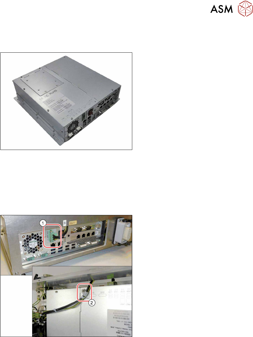
Fig.86: BoxPC ABP402-A CPU1020E 2xPCI SSD (iBase)
●
BoxPC ABP402-A CPU1020E 2xPCI
SSD (iBase) [03120423‑xx]
This newer version replaces the following
older versions:
Control Computer BoxPC 627B complete
[03055280‑xx]
Control Computer BoxPC 627C
[03094731‑xx]
Preparatory work...
► Turn off and disconnect the HCS II. See 3.1 "Turn off and disconnect the HCS II" [}19].
► Perform the steps described in section 3.4 "Access to the spare parts of the HCS II Control
Box" [}21].
Removal
Fig.87: Removal 1
► Carefully unplug the power cable(1)
(screwed) on the rear side.
► Remove the cable clamp(2) on the up-
per side.
5 Service work – HCSII Control Box
5.6 Replacing the BoxPC ABP402-A (iBase)
60 Service Manual SIPLACE Head Care Station II 11/2019
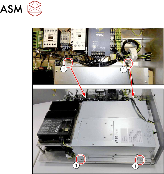
Fig.88: Removal 2
► Remove the four screws(1).
► Carefully remove the BoxPC.
Installation
► Follow the removal instructions in reverse order for installation.
► The BoxPC is supplied without cards. If required, these must be removed from the old BoxPC
and fitted in the new one or ordered as new parts.
5.7 "Replacing the CAN card" [}61]
5.8 "Replacing the Hotlink Interface" [}63]
► Replace any cable ties which you have removed.
► For software installation (newest operating system and HCS software) please read the corres-
ponding installation manual.
5 Service work – HCSII Control Box
5.7 Replacing the CAN card
Service Manual SIPLACE Head Care Station II 11/2019 61
5.7 Replacing the CAN card
Parts
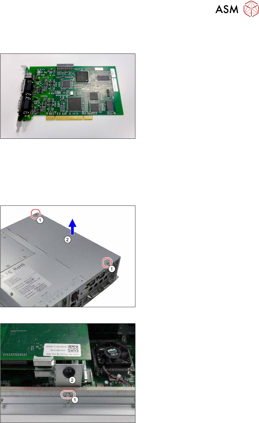
Fig.89: CAN card COM168V2-PCI
●
CAN card COM168V2-PCI
[03079973‑xx]
Preparatory work...
► Turn off and disconnect the HCS II. See 3.1 "Turn off and disconnect the HCS II" [}19].
► Perform the steps described in section 3.4 "Access to the spare parts of the HCS II Control
Box" [}21].
Removal
Fig.90: Removal 1
► Remove the two screws(1).
► Open the cover(2).
Fig.91: Removal 2
► Remove the screw(1).
► Carefully remove the PCB support(2).