80S-20用户手册 - 第150页
4 Placement functions SIPLACE 80S-20 /F4 User Manual 4.1 Setup display Software version S R.407.xx 01/2001 US E dition 150 4.1.1 "Set up location x" view 4 Å Clic k on the icon in the tool bar in th e Main vi e…
SIPLACE 80S-20/F4 User Manual 4 Placement functions
Software version SR.407.xx 01/2001 US Edition 4.1 Setup display
149
4 Placement functions
4.1 Setup display
If the cluster has been specified with its corresponding setup, then the setup of each of the 4
locations can be displayed in this view.
4
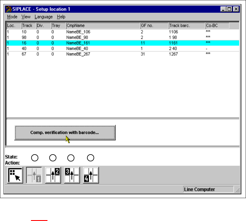
Fig. 4.1 - 1 ’Setup location 1’ view
Key to Fig. 4.1 - 1
(1) Display setup for location 1
(2) Display setup for location 2
(3) Display setup for location 3
(4) Display setup for location 4
1
2
3
4
4 Placement functions SIPLACE 80S-20/F4 User Manual
4.1 Setup display Software version SR.407.xx 01/2001 US Edition
150
4.1.1 "Setup location x" view
4
Å Click on the icon in the toolbar in the Main view.
The user interface switches to the "Setup location x" view.
The setup data for the current location is presented in the display area in tabular form.
NOTE
The view is the same for each location. 4
4.1.1.1 Meaning of the entries in the setup table
– Loc.
The number of the location whose setup is to be displayed is entered in this column. (See
Chapter 3
, Fig. 3.1 - 2 for the position of the locations)
– Track
The number of the track on which the corresponding feeder or waffle pack tray is located is
entered here.
– Div.
The number of the feeder division from which the component in the corresponding feeder is to
be picked up, or the number of the waffle pack tray compartment from which the component is
picked up is entered in this column.
– Tray
The number of the level in the waffle pack tray from which the component is picked up is en-
tered in this column.
(Only valid for automatic placement machines with wafflepack changers).
– CmpName
The name of the corresponding component is entered in this column.
– GF no.
The number of the package form for the corresponding component is entered here.
– Track barc.
The track barcode assigned to the corresponding track is entered in this column.

SIPLACE 80S-20/F4 User Manual 4 Placement functions
Software version SR.407.xx 01/2001 US Edition 4.1 Setup display
151
– CO-BC
This column shows whether or not a component barcode has been specified for the corre-
sponding component in the setup using the "***" or "-" symbol.
*** A barcode is specified for the component.
The "Comp. verification with barcode ..." button is active when you click
on these lines in the table (see Section 4.1.2
). 4
- No barcode is specified for the component.
(The "Comp. verification with barcode ..." button is not active). 4
4.1.2 Component verification with barcode
You prevent a track from being refilled with the wrong components with this function when refilling
components with a specified component barcode.
The operator reads the track barcode and then the component barcode with the barcode reader
(see Chapter 12
) . The two barcode assignments are compared with the help of the SC software.
Incorrect assignments are not accepted. 4
4
Requirements
– The barcode reader must be connected to the station computer.
– The "Track BC" option must be activated on the line computer (in the configuration editor) for
the corresponding station. (Only then will the "Component verification with barcode" option be
displayed in the machine options on the station computer).
– The barcodes for the corresponding components must have been entered on the line computer
with the help of the component editor.
(A maximum of 6 different barcodes can be entered for a component at the present time).
– The "Component verification with barcode" option must be active in the machine options.
4
Procedure
Å Open th e Options menu in the Main view and click on the Machine options ... menu option.
The "Machine options" window is opened (see Chapter 3
).
Å Activate the checkbox for "Component verification with barcode".
Å Click on Apply. The window closes.
Å Switch the user interface to the "Setup location x" view.
Å Click on the icon in the toolbar for the desired location (see Fig. 4.1 - 1).