80S-20用户手册 - 第214页
6 Vision functions SIPLA CE 80S-20/F4 User Manual 6.1 The vision s ystems on the placement machine Software v ersion SR.407.xx 01/2001 US Edition 214 6 Fig. 6.1 - 3 Component camera system on the 12-segment Collect&P…

SIPLACE 80S-20/F4 User Manual 6 Vision functions
Software version SR.407.xx 01/2001 US Edition 6.1 The vision systems on the placement machine
213
6.1.1 Component vision module on the 12-segment Collect&Place head
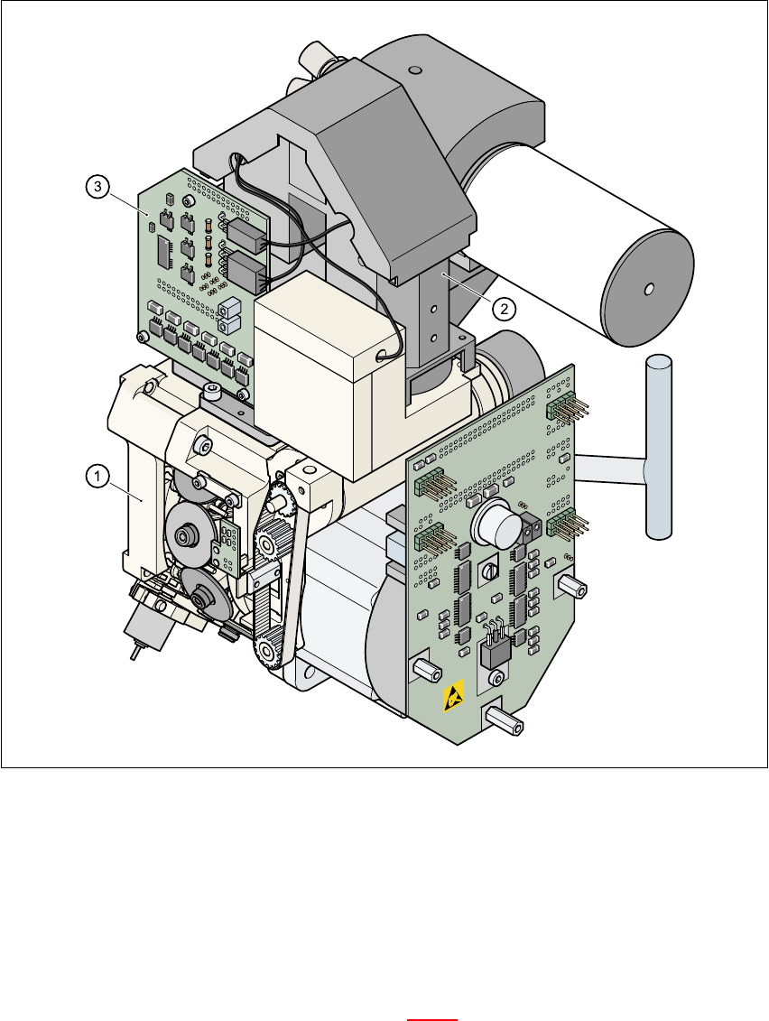
The component vision module (see item 2 in Fig. 6.1 - 3) essentially consists of the following mod-
ules: 6
– Optical lens
– CCD chip for creating an electronic image of the component
– CCD camera amplifier
– Three illumination levels – flat, average and steep – for optimum illumination of a wide
range of component shapes
–“Illumination control” board for setting the intensity of the individual illumination levels.
6
The component camera system is fastened to the top of the Collect&Place head using four hexa-
gon socket-head screws. It is then held in place by two parallel pins. 6
The component camera system can be used to optically center and place components ranging
from 0402 up to and including PLCC 44 in size. The components therefore vary in size between
1.0mm x 0.5mm and 18.7mm x 18.7mm, and from 0.3mm and 6mm thick. The minimum lead
pitch can be as little as 0.5mm. 6
6
6 Vision functions SIPLACE 80S-20/F4 User Manual
6.1 The vision systems on the placement machine Software version SR.407.xx 01/2001 US Edition
214
6
Fig. 6.1 - 3 Component camera system on the 12-segment Collect&Place head
(1) 12-segment Collect&Place head
(2) 24x24 component camera
(3) Component illumination control board
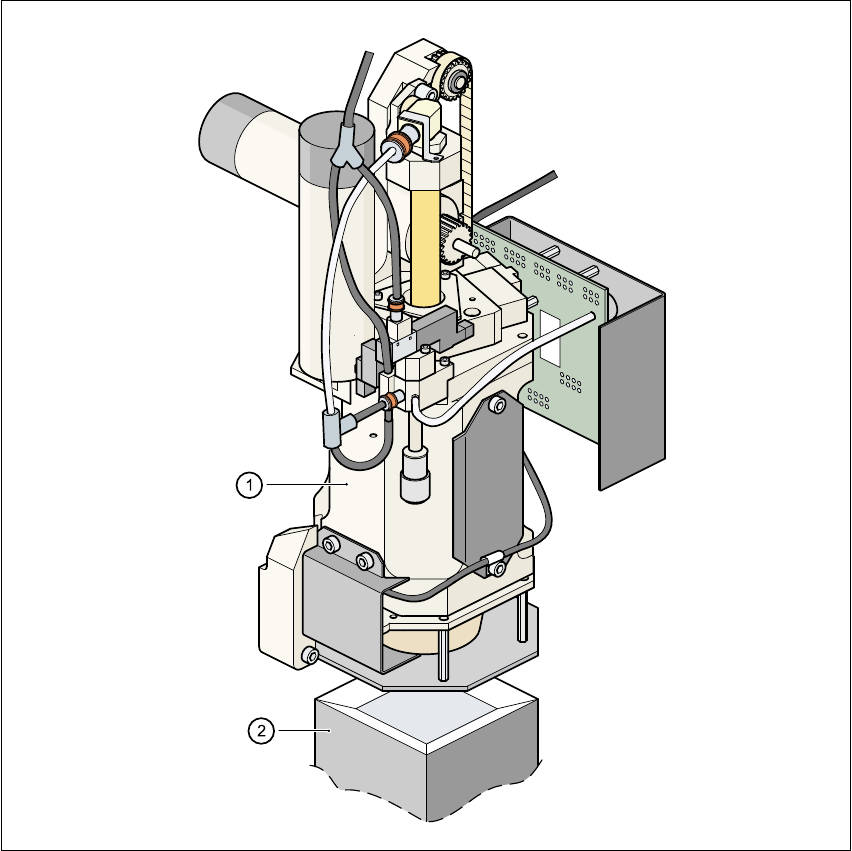
6.1.2 Component camera system on the Pick&Place head
The component camera system (see item 2 in Fig. 6.1 - 4) essentially consists of the following
modules: 6
– Optical lens
– CCD chip for creating an electronic image of the component
SIPLACE 80S-20/F4 User Manual 6 Vision functions
Software version SR.407.xx 01/2001 US Edition 6.1 The vision systems on the placement machine
215
– CCD camera amplifier
– Three illumination levels – flat, average and steep – for optimum illumination of a wide
range of component shapes
–“Illumination control” board for setting the intensity of the individual illumination levels.
6
Fig. 6.1 - 4 Component camera system on the Pick&Place head
(1) Pick&Place head
(2) Fine pitch vision module
6
6
6