80S-20用户手册 - 第329页
SIPLACE 80S -20/F4 User Manual 6 Vision functions Software version SR.407.xx 01/2001 US Edition 6.6 Test Component 329 Use package form edges 6 – for rotation wi ndows The packa ge form edges can be us ed to opt imally p…
6 Vision functions SIPLACE 80S-20/F4 User Manual
6.6 Test Component Software version SR.407.xx 01/2001 US Edition
328
6.6.4.17 ’Row’ measuring mode
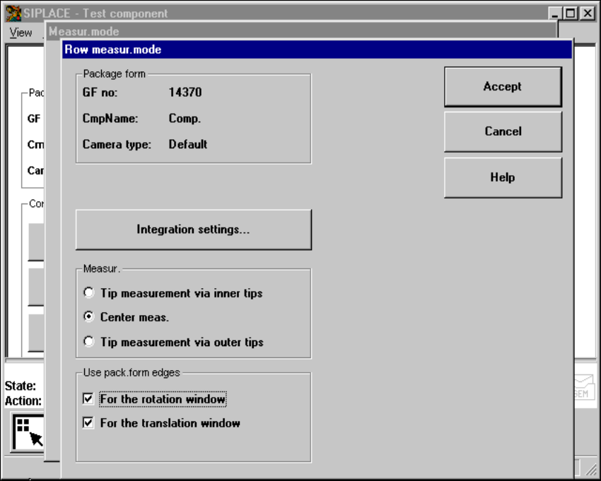
Click on the ‘Setting’ field in the Row measuring mode menu to call up the following menu: 6
6
Fig. 6.6 - 37 Measuring mode option, Row measuring mode menu
This menu is used to 6
– specify the lead measuring method.
– use the package form edges for the rotation windows and/or translation windows.
Measurement 6
If the inner lead tips are mapped better than the outer tips, for example, if a shiny lead is bent up-
wards slightly, you can select one of the following options: 6
– measuring the tips via the inner tips of the leads, for bases, for example
– center of the lead, center measurement, for PLCC, SOJ, for example
– measuring the tips via the outer tips of the leads, for QFP, SOT, SO, for example
SIPLACE 80S-20/F4 User Manual 6 Vision functions
Software version SR.407.xx 01/2001 US Edition 6.6 Test Component
329
Use package form edges 6
– for rotation windows
The package form edges can be used to optimally position the rotation windows. However, to
do this, the package form edge must be visible and it must not contain a row of leads (eg white
plugs).
– for translation windows
The package form edges can be used to optimally position the translation windows. However,
to do this, the package form edge must be visible and it must not contain a row of leads.
PLEASE NOTE:
Do not use measurement mode Row together with measurement mode Size. 6
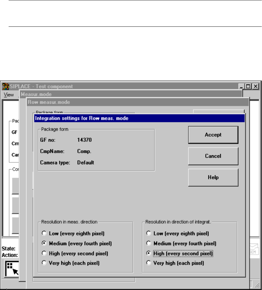
Integration settings 6
Once you have clicked on the ‘Integration settings’ field, the Row measuring mode integration
settings menu will appear on screen. 6
6
Fig. 6.6 - 38 Measuring mode option, Row measuring mode integration settings menu
6 Vision functions SIPLACE 80S-20/F4 User Manual
6.6 Test Component Software version SR.407.xx 01/2001 US Edition
330
Measuring times can be reduced by lowering the resolution in the measuring or integration direc-
tion. However, you must ensure that the structure to be analyzed has a sufficient number of pixels.
Otherwise, the measuring quality will be compromised. We recommend to choose a very high or
high resolution. 6
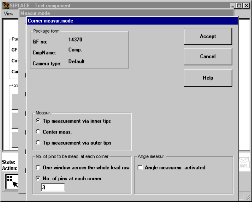
6.6.4.18 ‘Corner’ measuring mode
Click on the ‘Setting’ field in the ‘Corner’ measuring mode to call up the Corner measuring mode
menu. 6
6
Fig. 6.6 - 39 Measuring mode option, Corner measuring mode menu
This menu is used to 6
– specify the lead measuring method.
– select the number of leads to be measured at each corner.
– switch the angle measurement on or off.