80S-20用户手册 - 第33页
SIPLACE 80S -20/F4 User Manual 1 Introduction Software vers ion SR.407.xx 0 1/2001 US Edit ion 1.5 Descript ion of the machine 33 1.5 Description of the ma chine 1.5.1 SIPLACE 80S-20 functional description The S-20 au to…

1 Introduction SIPLACE 80S-20/F4 User Manual
1.4 Revision index Software version SR.407.xx 01/2001 US Edition
32
1.4.8 Overview of the revisions in the 01/2001 US edition
1
New or modified Chapter / Section
Technical data – noise emissions 1.8.4
Technical data – PCB vision module 1.14.3
Technical data – dual conveyor 1.15.3
Warning signs on the placement system 2.1.5
Additional warning signs for the NAFTA region 2.1.6
Safety instructions for processing capacitors based on powdered metal 2.1.15
Overview 10.1
Safety instructions for processing capacitors based on powdered metal 10.1.1
12 mm S module for capacitors based on powdered metal, model C/D 10.2.4
12 mm S module for capacitors based on powdered metal, model E 10.2.5
88mm S module (80F4) 10.2.12
Fine calibration 11.12
Vacuum tooling 11.13
SIPLACE 80S-20/F4 User Manual 1 Introduction
Software version SR.407.xx 01/2001 US Edition 1.5 Description of the machine
33
1.5 Description of the machine
1.5.1 SIPLACE 80S-20 functional description
The S-20 automatic placement system is a high-performance placement system with two gantry
axis systems. A PCB vision system and a star-shaped 12-segment Collect&Place head are
mounted on each gantry. Collect&Place heads equipped with a component vision system pick up
the components from stationary feeder modules and place them onto the PCB clamped in the
PCB conveyor. 1
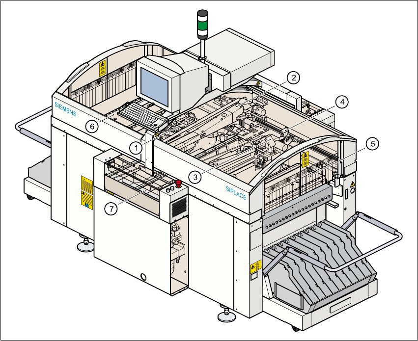
Fig. 1.5 - 1 General view of the 80S-20 placement system
(1) 12-segment Collect&Place head with component vision module (gantry 1)
(2) Gantry 1 with PCB vision module
(3) 12-segment Collect&Place head with component vision module (gantry 2)
(4) Gantry 2 with PCB vision module
(5) Stationary component supply (location 1)
(6) Stationary component supply (location 3)
(7) PCB conveyor (dual conveyor option)
1 Introduction SIPLACE 80S-20/F4 User Manual
1.5 Description of the machine Software version SR.407.xx 01/2001 US Edition
34
The concept behind the automatic placement system 1
– with its stationary feeder modules,
– PCBs that do not move during placement
– and positionable placement heads
has a number of significant benefits: 1
– For example, the flexible 12-segment Collect&Place heads combined with automatic nozzle
changers enable the nozzle configuration to be changed temporarily and automatically
adapted to receive different component sizes.
– You can also optimize the traversing paths and the placement sequence.
– With stationary feeder modules, even the tiniest components are picked up reliably.
– The components cannot slip on the PCB during placement (as is often the case with moving
PCBs) since the PCB does not move.
– Sophisticated optical centering systems (vision systems) for components and PCBs also en-
sure high component positioning accuracy.
– Components can be topped up and tapes can be spliced without stopping the machine.
– Prepared component tables enable the placement system to be retooled without long stop-
pages.