80S-20用户手册 - 第361页
SIPLACE 80S -20/F4 User Manual 6 Vision functions Software version SR.407.xx 01/2001 US Edition 6.8 Recommenda tion for visually centering components 361 6.8.2 General recommendations for center ing flip-chip s, BGAs and…
6 Vision functions SIPLACE 80S-20/F4 User Manual
6.8 Recommendation for visually centering components Software version SR.407.xx 01/2001 US Edition
360
6.8 Recommendation for visually centering compo-
nents
6.8.1 Visually centering flip-chips
6.8.1.1 Entering the data on the line computer
Å Describe the ball radius.
Å Select tolerances of between 10 % and 20 %.
6.8.1.2 Setting the parameters on the station computer
Å Under the’ Illumination Option’ in the ’Test Component Menu’, select the flat illumination plane
and set the brightness values to between 200 and 255. Do NOT use transformation tables to
do this.
Å Select a positive ball contrast under the Ball Image Option (see page 315).
PLEASE NOTE 6
If a lot of ’non-ball structures’ are identified as ball structures (they can be recognized by the
small crosses), increase the ball contrast. The number of crosses can be estimated in the
’Measure’ menu during the grid measurement. 6
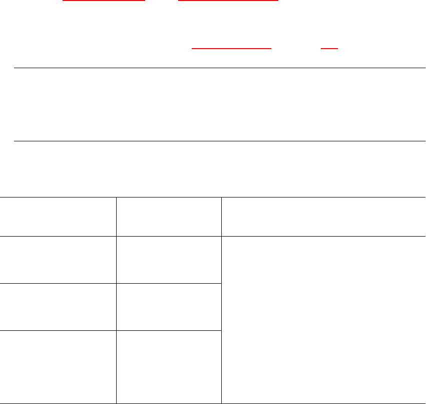
6.8.1.3 Recommended sequence of measurements for visually centering flip-chips
Size measuring mode Grid measuring
mode
Ball measuring mode
Resolution for calculat-
ing the angle:
low resolution
For single measure-
ment:
3 balls per corner
Standard
ball detection:
Hex value P1 = 80
Fast
ball detection:
Hex value P1 = A0
PLEASE NOTE:
Switch Ball mode off if it is not necessary
to measure all the balls.
In this case, P1 must be set to 80 in Grid
mode.
Resolution in the mea-
suring direction:
medium
For multiple mea-
surement:
5 balls per corner
Resolution
in the integration
direction:
medium
Hex value P1 = 80
Tab. 6.8.1 Recommended sequence of measurements for visually centering flip-chips

SIPLACE 80S-20/F4 User Manual 6 Vision functions
Software version SR.407.xx 01/2001 US Edition 6.8 Recommendation for visually centering components
361
6.8.2 General recommendations for centering flip-chips, BGAs and screening
plates
6.8.2.1 Setting the ball contrast parameters
If you select a high value for the ’Ball image’ option in the ’Test component’ menu, this will reduce
the effect of any defective structures. It does mean, however, that there is a possibility that not
every ball will be detected. 6
Set a lower value to ensure that all the balls are detected. This will reduce the reject rate, but the
measurement will take longer.
6.8.2.2 Setting the ball radius parameters
Enter the ball radius on the line computer. This value is automatically reduced by 20 % since the
vision system will detect balls even if the specified dimensions are smaller then their actual phys-
ical dimensions. 6
So, set the ball radius on the station computer and then adjust the quality in the ’Measure’ menu.6
– If no crosses are displayed on the ball, the radius is incorrect or the contrast is too high.
– If several crosses are displayed on a ball, then the radius has been entered incorrectly in the
’Measure’ menu.
PLEASE NOTE 6
We recommend that you select a radius on the line computer that is slightly larger than the
theoretical value and then adjust it in the ’Ball image’ menu. 6
6.8.2.3 Setting the case shape dimension parameters on the station computer
For high-contrast flip-chips and BGAs, you can reduce the physical case shape dimension to the
square surrounding the balls (’Case dimension’ option). This will reduce the measuring time, al-
though it can only be used for single measurements. Size mode must also be active. 6
6.8.3 Visually centering flip-chips
6.8.3.1 Setting the parameters on the station computer
Under the’ Illumination Option’ in the ’Test Component Menu’, select: 6
– a value of around 50 for the medium illumination plane
– a value of around 20 for the steep illumination plane
6 Vision functions SIPLACE 80S-20/F4 User Manual
6.8 Recommendation for visually centering components Software version SR.407.xx 01/2001 US Edition
362
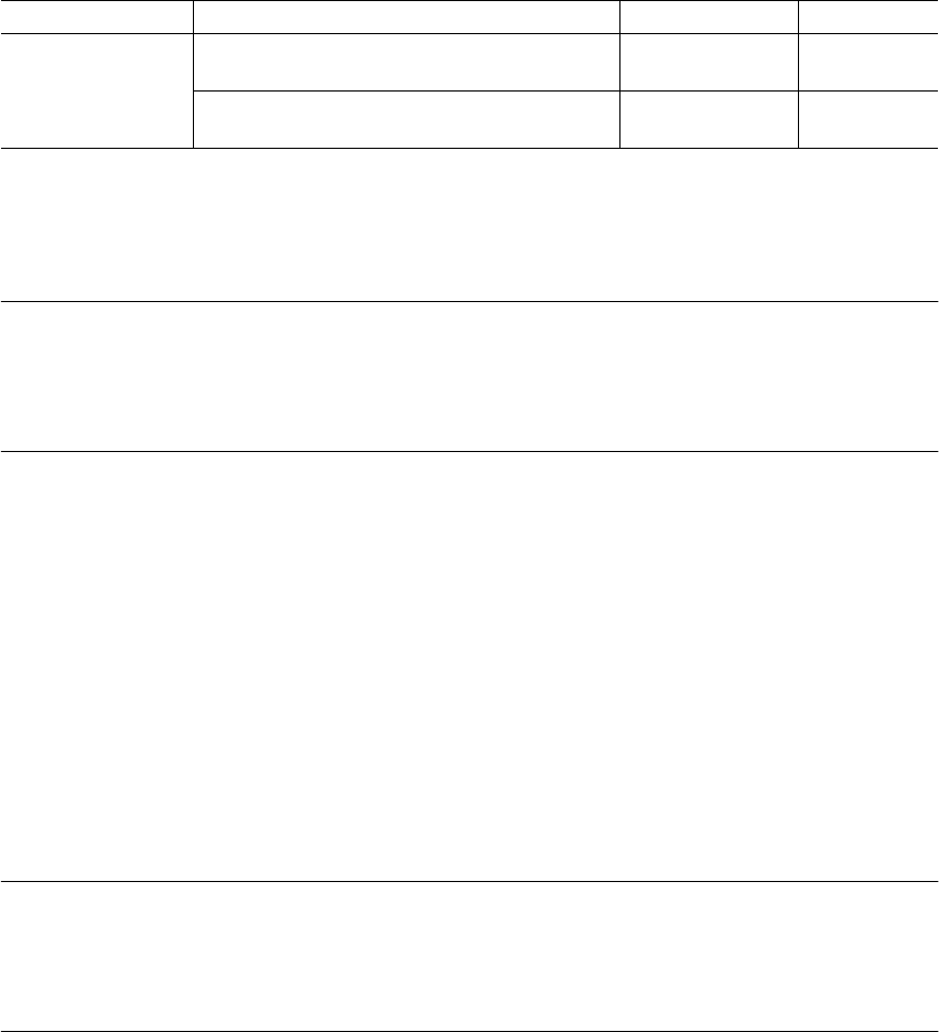
6.8.3.2 Recommended sequence of measurements for optically centering bare dies
6.8.4 Centering shielding plates using the vision system
PLEASE NOTE:
Do not describe shielding plates as BGAs unless they are larger than 32 mm x 32 mm in size. This
is the maximum permissible size for single measurements. If BGA mode is used to describe
shielding plates, the holes will be measured as well. 6
6.8.4.1 Data input on the line computer
Å Describe the radius of the holes.
Å Select a value between 10% and 20 % for the tolerance.
6.8.4.2 Setting parameters on the station computer
Å Select the ‘Illumination’ option from the ‘Test component’ menu, and then select the flat, aver-
age and steep illumination levels.
Å Select the ‘Ball illustration’ option from the ‘Test component’ menu, and then select a negative
ball contrast.
PLEASE NOTE:
Reduce the negative value if you find that a lot of ‘non-ball structures’ are recognized as ball struc-
tures (which can be identified by the tiny cross marks). The number of crosses can be estimated
during the grid measurements by selecting the ‘Measure’ menu. 6
Measuring mode Size Grid Ball
Settings
Resolution in measuring direction:
very high
——
Resolution in integration direction:
very high
——
Tab. 6.8.2 Recommended sequence of measurements for optically centering bare dies