80S-20用户手册 - 第446页
10 Component handling SIPLACE 80S-20 /F4 User Manual 10.5 Used tape cutter Software version SR. 407.xx 01/2001 US E dition 446 PLEAS E NOTE On SIPLA CE automa tic placeme nt system s, only us e the tape feeder mod ules s…
SIPLACE 80S-20/F4 User Manual 10 Component handling
Software version SR.407.xx 01/2001 US Edition 10.5 Used tape cutter
445
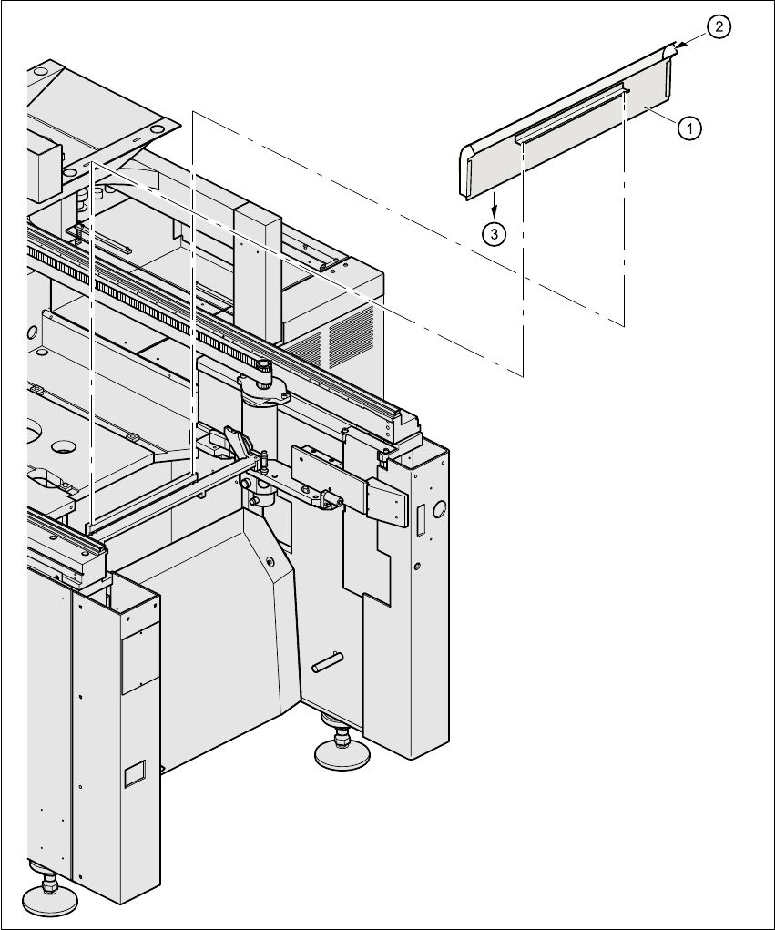
10.5.2 Inserting the tape into the tape cutter
10
Fig. 10.5 - 2 Inserting the tape into the tape cutter
(1) Used tape channel (2) Used tape
(3) Tape feeder module (4) To used tape cutter
10 Component handling SIPLACE 80S-20/F4 User Manual
10.5 Used tape cutter Software version SR.407.xx 01/2001 US Edition
446
PLEASE NOTE
On SIPLACE automatic placement systems, only use the tape feeder modules specified for these
machines. The used tape channel which removes the used tape is located upstream of the feeder
modules. 10
Å Insert the tape into the feeder as described in the corresponding section.
Å Guide the used tape into the used tape channel of the cutter as described in Fig. 10.5 - 2
The used tape guide channels are located upstream of the feeder modules
(see pos. 1 in fig. 10.5 - 2
). They are positioned directly above the used tape cutters (see pos. 3
in fig. 10.5 - 2
). 10
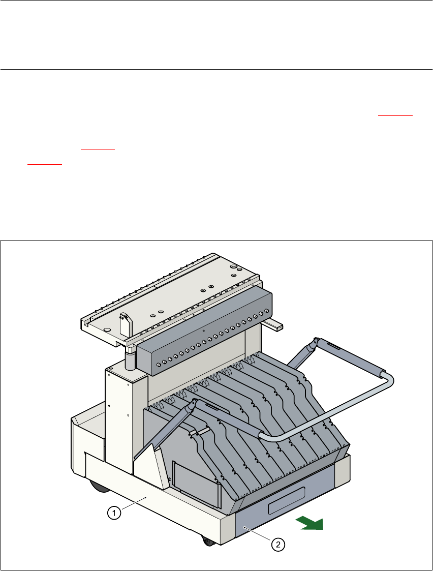
The tape is automatically guided through the used tape guide channel into the used tape cutter
below. There, the tape is shredded by the pneumatically-actuated cutting blade. The waste tape
then passes via the waste tape chute into the waste container. 10
10
Fig. 10.5 - 3 Used tape container in the component changeover table, withdrawable
(1) Component changeover table
(2) Used tape container, withdrawable
SIPLACE 80S-20/F4 User Manual 10 Component handling
Software version SR.407.xx 01/2001 US Edition 10.6 Component table, mobile
447
10.6 Component table, mobile
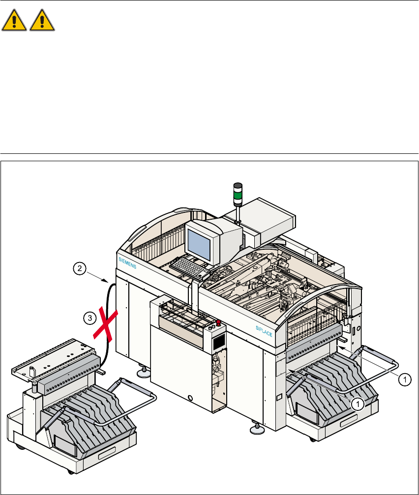
10.6.1 Safety instructions for docking and undocking the mobile component table
WARNING 10
Å Never reach into the gap between the component tables and the placement system frame
while the machine is running (item 1).
Å Always check that the component table is docked on the placement system before connecting
or disconnecting the component table power cable at the socket on the placement system
(item 2).
Å NEVER connect the component table connecting cable to the socket on the placement system
and then operate the component table via the external compressed air control unit (item 3).
Fig. 10.6 - 1 Safety instructions for the mobile component table