80S-20用户手册 - 第466页
11 Station extensions /Hardware SIPLACE 80S-20 /F4 User Manual 11.1 Nozzle changer for the 12-segment C ollect&Place head Sof tware version SR.407.xx 01/2001 US Edition 466 11 Fig. 1 1.1 - 1 Overview of the nozz le c…

SIPLACE 80S-20/F4 User Manual 11 Station extensions /Hardware
Software version SR.407.xx 01/2001 US Edition 11.1 Nozzle changer for the 12-segment Collect&Place head
465
11 Station extensions /Hardware
11.1 Nozzle changer for the 12-segment Collect&Place
head
11.1.1 Overview
S-20 11
The placement system is supplied as standard with two Collect&Place heads. As an option, a noz-
zle changer can be installed for each Collect&Place head. 11
F
4
11
A nozzle changer for the 12-segment Collect&Place head can be installed, without loss of feeder
locations, to the left of the PCB conveyor. 11
This enables the nozzle configuration to be changed quickly, thus allowing the Collect&Place head
to be quickly adapted to the needs of the placement process. 11
The nozzle changer consists of at least one and up to seven magazines, each with twelve nozzle
holders (see Fig. 11.1 - 1
). The magazines are mounted on a common WPC tray.Each magazine
is centered using two parallel pins, and fixed in place with a screw. 11
11
11.1.2 Technical data - Nozzle changer for the 12-segment Collect&Place head
11
Nozzle changer for the 12-segment Collect&Place head
Dimensions (length x width x height) 560 mm x 60 mm x 46 mm
Number of nozzle holders min.12 / max. 84
Nozzle types 7xx
Time required to open and close the locking plate < 200 ms
Capacity of the reject bin approx. 50 nozzles
Pneumatic system 5.3 bar air line
11 Station extensions /Hardware SIPLACE 80S-20/F4 User Manual
11.1 Nozzle changer for the 12-segment Collect&Place head Software version SR.407.xx 01/2001 US Edition
466
11
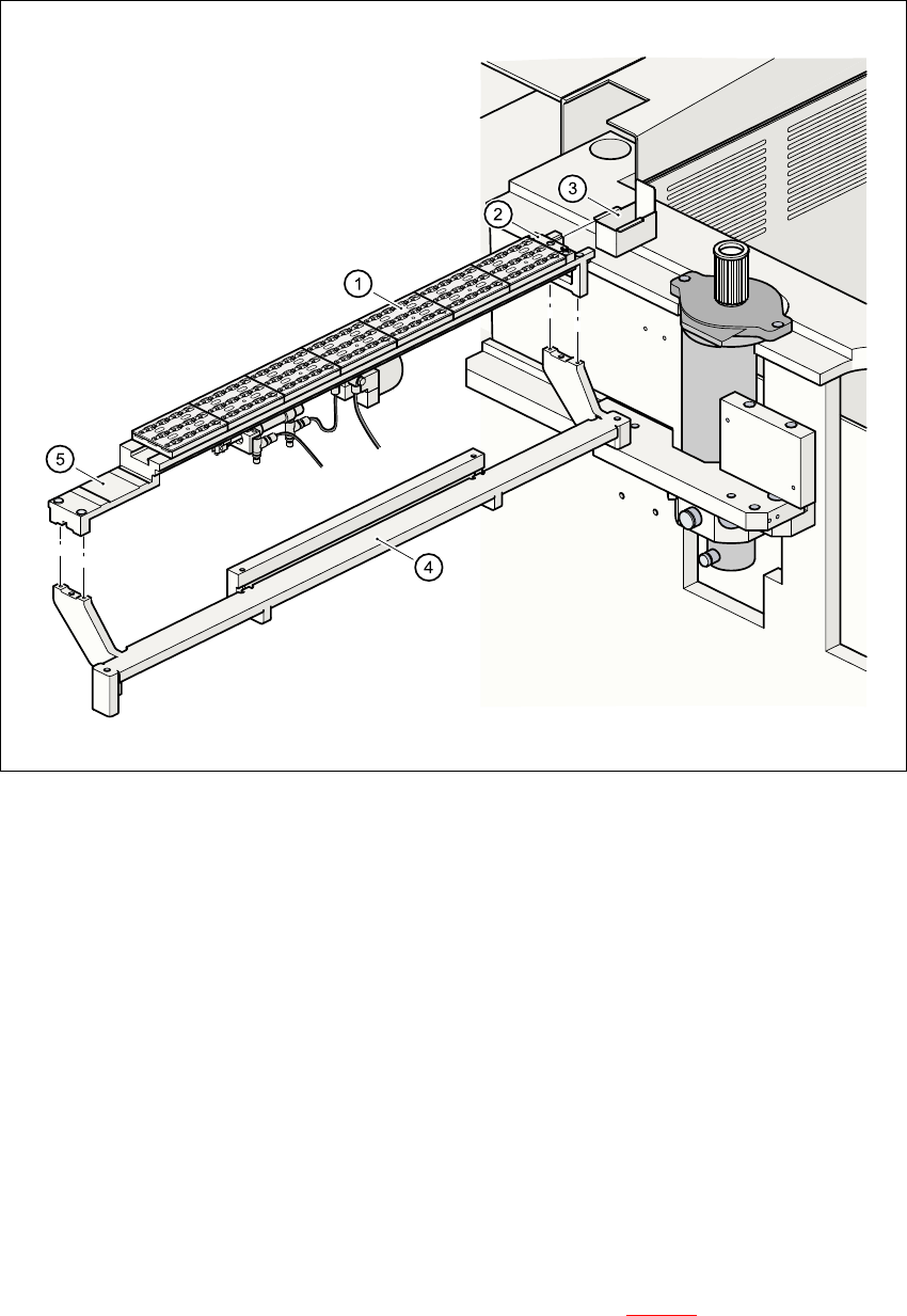
Fig. 11.1 - 1 Overview of the nozzle changer for the 12-segment Collect&Place head
11.1.3 Basic principles
The nozzles are seated in nozzle holders, and are fixed in place by a movable locking plate. The
locking plate can be moved up to 6 mm by a pneumatic cylinder. All the nozzles are either clamped
or released, depending on the position of this plate. The locking plate is always left in the “closed”
position if no nozzle exchange is taking place. 11
All the nozzle changer magazines have a position fiducial for position recognition purposes. The
magazine locations on the nozzle changer are identified by numbers 1 to 7. The nozzle holders in
the magazines are numbered consecutively from 1 to 12 (see Fig. 11.1 - 3
). 11
(1) Magazine (2) Reject device for nozzles
(3) Collecting bin for rejected nozzles (4) Nozzle changer, base unit
(5) Nozzle changer, support 11

SIPLACE 80S-20/F4 User Manual 11 Station extensions /Hardware
Software version SR.407.xx 01/2001 US Edition 11.1 Nozzle changer for the 12-segment Collect&Place head
467
PLEASE NOTE 11
Special magazines are available upon request, and are given a special identification. Please con-
tact Siemens PL EA 1E to discuss. 11
Picking up a nozzle 11
– The Collect&Place head Z-axis moves down.
– The locking plate (item 3 in Fig. 11.1 - 2
) opens and releases the nozzles.
– The nozzle is picked up from the sleeve of the Collect&Place head.
– The Z-axis moves up.
Returning a nozzle 11
– The locking plate (item 3 in Fig. 11.1 - 2) opens and releases the nozzles.
– The Collect&Place head Z-axis moves down and releases the nozzle.
– The locking plate closes.
– The Collect&Place head Z-axis moves up.
Rejecting defective nozzles 11
– At the reject device (item 2 in Fig. 11.1 - 1), the Collect&Place head Z-axis moves down 14 mm,
and thus feeds the defective nozzle into the hole in the reject device.
– The Z-axis moves up again, and the nozzle is removed from the sleeve by spring wires.
– The nozzle drops into the collecting tray of the empty tape track (item 3 in Fig. 11.1 - 1
).