80S-20用户手册 - 第49页
SIPLACE 80S -20/F4 User Manual 1 Introduction Software version SR.407.xx 01/2001 US Edition 1.11 Overview of the modules - controls 49 1.1 1 Overview of the modules - controls 1.1 1.1 Controls 1 Fig. 1.1 1 - 1 Overview o…

1 Introduction SIPLACE 80S-20/F4 User Manual
1.10 Setting up the placement machine Software version SR.407.xx 01/2001 US Edition
48
1.10.6 Setting up the placement machine
Å Raise the machine using the pallet jack, and adjust the feet until there is a gap of 830 mm be-
tween the top edge of the PCB conveyor and the bottom edge of the feet.
Å Leave a gap of 1 to 3 mm between the PCB conveyors of the machine.
Å Use a cord pulled tight to ensure that all the placement machines are exactly in line with one
another.
Å Adjust each machine using a spirit level with an accuracy of 0.02 mm/m.
Å Lock the feet in position.
Å Check the machine again using the spirit level, and correct the settings, if necessary.
CAUTION
Make sure that you remove all the shipping braces from the machine. 1
Å Fit any components that were dismantled for dispatch.
Å Connect all the electrical and pneumatic lines.
RISK OF DEATH
The electrical connection work must be carried out ONLY by appropriately trained and certi-
fied personnel. 1
SIPLACE 80S-20/F4 User Manual 1 Introduction
Software version SR.407.xx 01/2001 US Edition 1.11 Overview of the modules - controls
49
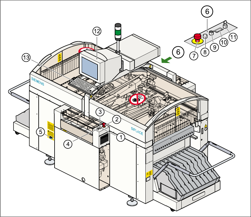
1.11 Overview of the modules - controls
1.11.1 Controls
1
Fig. 1.11 - 1 Overview of the modules - controls
(1) Operator panel, input conveyor side (2) Emerg. stop mushroom-head push-button
(3) Start button (white) (4) Stop button (black)
(5) Main switch (6) Operator panel, output conveyor side
(7) Emerg. stop mushroom-head push-button (8) Start button (white)
(9) Stop button (black) (10) Component counter
(11) Key switch (12) Touchscreen monitor
(13) Keyboard with trackball 1

1 Introduction SIPLACE 80S-20/F4 User Manual
1.11 Overview of the modules - controls Software version SR.407.xx 01/2001 US Edition
50
1.11.2 Description
All the controls can be reached by a 1.60 m tall person. 1
Main switch 1
The main switch is used to switch the power supply to the machine on and off. 1
RISK OF DEATH
Some parts inside the placement machine carry potentially lethal voltages - even when switched
off at the main switch. 1
Key switch 1
In normal mode, the key switch is set to "0". The key should be removed and kept in a safe place.
It must only be turned to position "I" (set-up mode) by authorized personnel, and then only for cer-
tain maintenance and servicing work. 1
Stop button 1
This button is used to stop the placement machine. 1
Start button 1
This button starts the machine after it has been switched on, or after faults have been eliminated. 1
Emergency stop mushroom-head push-button 1
The emergency stop mushroom-head push-button latches into place when it is pressed. The
power supply for the gantry axes, component tables, conveyor belts, and cutting devices is inter-
rupted, and the voltage to the star axes of the placement heads is reduced. The button must be
turned to release it. 1
Component counter 1
The component counter displays the number of components processed. 1
Station computer, monitor and keyboard 1
The station computer, monitor and keyboard are mounted on a rotating console on the placement
machine’s central cross-beam. The station computer is a desktop model with a Pentium proces-
sor. The operating system is WINDOWS NT 4.0. The SIPLACE graphical user interface, which is
based on the Windows standard, is used to operate and monitor the machine. A color touchscreen
monitor with a resolution of 640 x 480 pixels provides the screen display. Both the keyboard and