80S-20用户手册 - 第494页
11 Station extensions /Hardware SIPLACE 80S-20 /F4 User Manual 11.7 Flip-chip vision m odule for the Pick & P lace head Software version SR.407.xx 01/2001 US Edition 494 1 1 .7 Flip-chip vision module for the Pick &a…
SIPLACE 80S-20/F4 User Manual 11 Station extensions /Hardware
Software version SR.407.xx 01/2001 US Edition 11.6 Nozzle changer for the Pick&Place head
493
Key to Fig. 11.6 - 2
– All the magazines have a position fiducial (item 1 in Fig. 11.6 - 2) for position recognition pur-
poses.
– The individual magazine locations are numbered consecutively from 1 to 4.
– The individual nozzle holders are numbered consecutively from 1 to 5 in each magazine.
– The nozzles are fixed in place in the holders by sprung hooks. The nozzles are either clamped
or released, depending on the direction of rotation of the Pick&Place head axis.
11.6.4 Notes on operation and maintenance
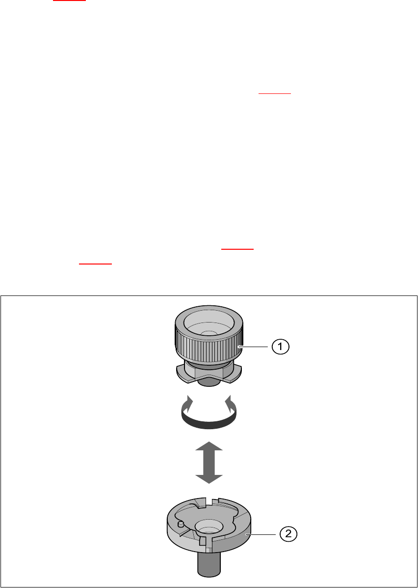
Å Use the nozzle removal tool (see point 1 in Fig. 11.6 - 3) to insert or exchange the nozzles
(point 2 in Fig. 11.6 - 3
).
Å Clean the nozzle changer as described in the maintenance instructions.
Fig. 11.6 - 3 Removing the nozzle from the nozzle changer
(1) Position fiducial (2) Nozzle holder
(3) Reject bin (4) Magazine 1 (standard)
(5) Magazine 2 to 4 (optional) 11
11 Station extensions /Hardware SIPLACE 80S-20/F4 User Manual
11.7 Flip-chip vision module for the Pick & Place head Software version SR.407.xx 01/2001 US Edition
494
11.7 Flip-chip vision module for the Pick & Place head
11
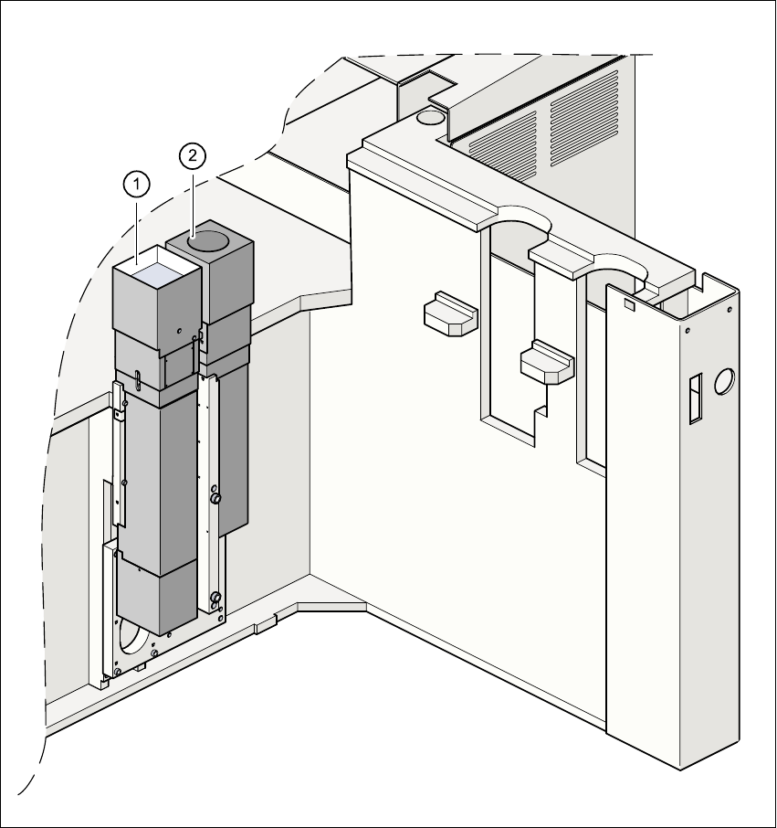
Fig. 11.7 - 1 Vision module for the Pick&Place head
(1) Fine-pitch vision module for the Pick &Place head
(2) Flip-chip vision module for the Pick&Place head
SIPLACE 80S-20/F4 User Manual 11 Station extensions /Hardware
Software version SR.407.xx 01/2001 US Edition 11.7 Flip-chip vision module for the Pick & Place head
495
11.7.1 Functional description
The flip-chip vision module increases the capability for processing fine-pitch and flip-chip compo-
nents with extremely fine lead pitches. This add-on module for the fine-pitch vision module in-
creases the resolution many times. The lighting layout is fundamentally different. At optimal
illumination, the images of bumps are as large as possible, and disruptive orthogonal structures
(as can occur on chip printed conductor tracks, for example) are suppressed. With less pro-
nounced disruptive structures, enhanced illumination intensity can be achieved by combining
lighting fixtures, resulting in high recognition reliability, even with the generally square connection
surfaces of ‘bumped’ flip-chips as used in conductive adhesive technology. Special search algo-
rithms are used to recognize the bumps in environments subject to disruption. 11
11.7.2 Safety instructions for the component vision modules on Fx machines
DANGER
NEVER modify or bypass safety devices on the Fx machine, or on the fine-pitch or flip-chip mod-
ule. 11
The optical radiation from the fine-pitch or flip-chip vision module conforms to laser class 1, pro-
vided that the module is permanently installed in the placement machine, and the protective hoods
are closed (EN 60825-1 and IEC 825). 11
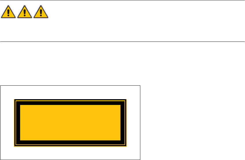
Fig. 11.7 - 2 Identification of laser class 1
Laser Class 1