80S-20用户手册 - 第511页
SIPLACE 80S-20/F4 User Manual 11 Station extensions /Hardware Software version SR.407.xx 01/2001 US Edition 11.9 Flux dispenser unit 511 1 1.9.6.1 Setting the dist ance between the dispensing needle and the PCB 11 Fig. 1…

11 Station extensions /Hardware SIPLACE 80S-20/F4 User Manual
11.9 Flux dispenser unit Software version SR.407.xx 01/2001 US Edition
510
CAUTION
When you unscrew the centering nozzle, make sure that you do not lose the two clamping parts
that hold the dispensing needle in the cylinder. 11
Å Loosen the centering nozzle.
Å Pull the cylinder lid away from the cylinder, and pull the complete dispensing needle out of the
cylinder.
Å Disconnect the dispensing needle hose from the valve of the dispensing pump.
Å Thread the new dispensing needle through the cylinder lid, through the cylinder and into the
centering nozzle. The tip of the dispensing needle must protrude approximately 3 mm from the
centering nozzle.
Å Tighten the centering nozzle once more.
Å Press the lid onto the cylinder.
Å Check the distance between the dispensing needle and the PCB. Press the down on the piston
– the distance must now be approximately 1 mm.
If this is not the case, you will have to reset the distance.
SIPLACE 80S-20/F4 User Manual 11 Station extensions /Hardware
Software version SR.407.xx 01/2001 US Edition 11.9 Flux dispenser unit
511
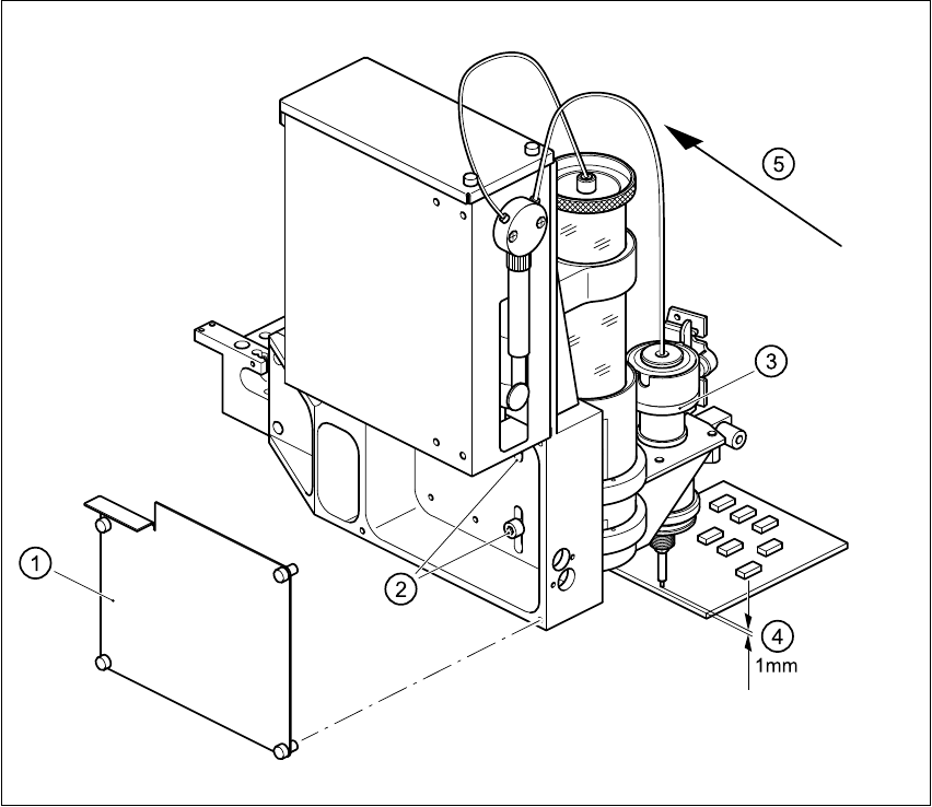
11.9.6.1 Setting the distance between the dispensing needle and the PCB
11
Fig. 11.9 - 5 Setting the distance between the dispensing needle and the PCB
11
Å Loosen the 4 fixing screws for the rear panel of the flux dispenser, and remove the panel.
Å Loosen the two fixing screws in the slots.
Å Press down on the lifting piston, and adjust the flux dispenser so that the distance between the
tip of the dispensing needle and the PCB is 1 mm.
(1) Rear panel with four fixing screws
(2) Two fixing screws for the flux dispenser
(3) Lifting piston
(4) Set a distance of 1 mm with respect to the PCB
(5) Press the flux dispenser right down against the stop
11 Station extensions /Hardware SIPLACE 80S-20/F4 User Manual
11.9 Flux dispenser unit Software version SR.407.xx 01/2001 US Edition
512
Å Push the flux dispenser against the side stop, and tighten the fixing screws.
Å Attach the rear panel.
11.9.7 User interface
PLEASE NOTE
Before the flip-chip component can be placed and the flux can be applied, a placement program
with flip-chip component must be created on the line computer and sent to the station computers
(see the UNIX user manual).
The Fluxing option must have been activated in the machine options on the station computer.
See Section 3.3.2.3 "Options" menu of the user manual. 11
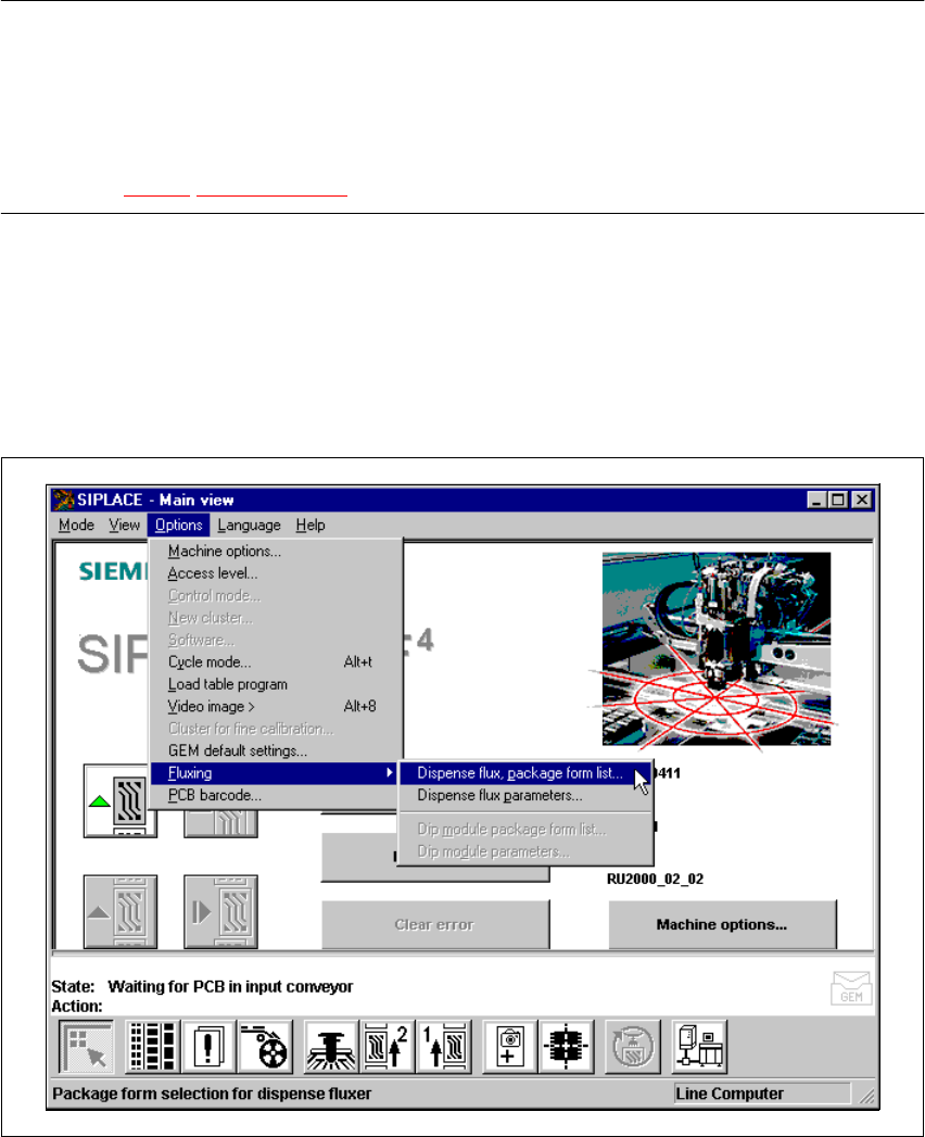
11.9.7.1 Package form list and parameters
Before the flux can be applied to a PCB for placing flip-chips, process data about the flip-chip must
be entered in a list, and general parameters about the flux dispenser must be entered on the sta-
tion computer. 11
Å Select the Fluxing submenu from the Options menu in the menu bar.
Fig. 11.9 - 6 Fluxing option