F5HM Circuit Diagrams.pdf - 第101页
3 Options Circui t Diagrams 101 001 17185-0 10101LD 3 Conver sion kit 1 10/20 8V for SIP LACE 80 S20 / S 23 / F4 / F5 (Sh. 3 o f 3) = Gepr. Norm Bearb. Urspr. Ers. f . Ers. d . Name SIEME NS AG + D 8 B F 3 A E 3 2 D C B …
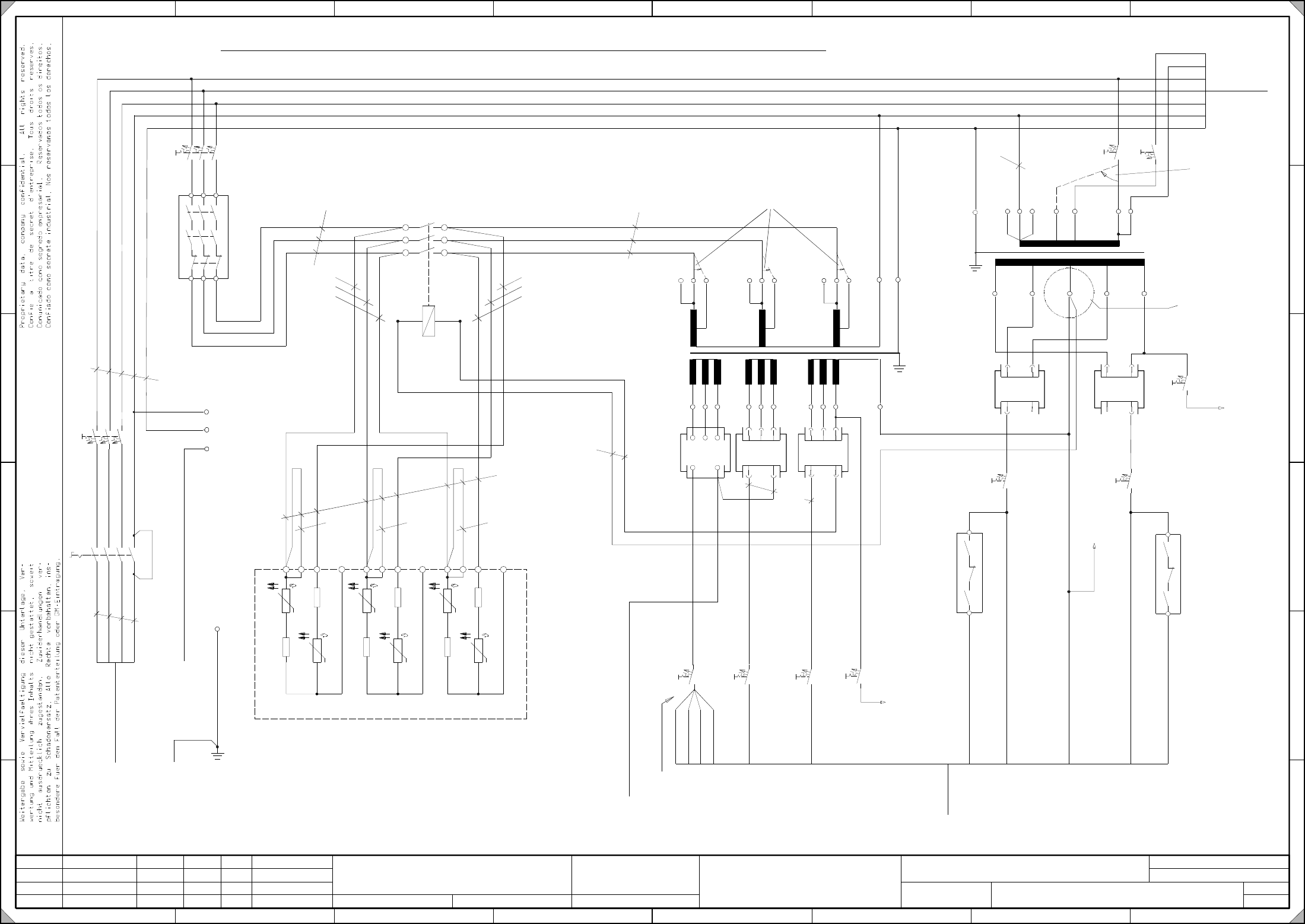
3 Options Circuit Diagrams 100
00117185-010101LD3 Conversion kit 110/208V for SIPLACE 80 S20 / S23 / F4 / F5 (Sh. 2 of 3)
=
Gepr.
Norm
Bearb.
Blatt
Urspr. Ers. f. Ers. d.Name
SIEMENS AG
Bl.
+
5
F
A
71
A
B
C
B
F
2
D
C
1 4
E
3
E
D
86
45
6 873
2
2
1,5mm
2
2,5mm
2
2,5mm
2
2,5mm
2
2,5mm
+
-
+
-
+
~
-
~
+
~
-
~
Pin1 => Pin7 Pin2 => Pin8 Pin3 => Pin9
2
2,5mm
2
1,5mm
2
1,0mm
2
2,5mm
2
2,5mm
2
2,5mm
2
2,5mm
2
1,0mm
2
10,0mm
2
2,5mm
2
4,0mm
2
1,5mm
A1
6
1
2
3
4
5
7
8
9
Pin6 => Pin4
V3(-)
2L-(0V)
2
4
6
1
3
5
11 12 13 14 21 22 23 24 31 32 33 34
zu
24
8
+5%
120
150
45
230
230
66
6A
2
F11
1
1
F3
10A
2
52
400
400
208
8369
V4
36A
N
PE
7
24
-5%
PE
N
12
V5
36A
6A
F10
2
1
T1
109
8
0
11
400
4
513
624
PE
16A
PE
F2
3313 23
624
513
N
X200
3
8
208
400
208
400
400
71
19
10A
2
F8
1
14
2L-
6L+
7L+
K2
GND
13
F9
10A
2
1
Q1
16A
F1
L3L1 L2 N
T3T1 T2 N’
2414 34
T2
K1
V1
~~ ~~~
V2
10A
~~~
V3
105
105
105
11 12
48
48
13 14 16
48
15
42
42
42
17 18
K2
23
0V
C506-W1
6
7
8
9
10
00300161
1L+
2L+
3L+
1
1
F5
2
10A
2
F6
1
F7
2
10A
10A
4L+
5L+
1
2
24V AC
24
40A
10A
-
24V AC
1
1L+
10
C502-W1
Y631-W1
Y631-W2
C511-W1
11
4
1L-
1L+
1L+
F4
20A
+
~
2
3
5
A2(-)
10.03.99
00117185-010101LD3
#
Berger
14.10.1998
14.10.98
14.10.98
01.
01.
01.
Tek
Wa
Wa
2
3
56R
K4
A1(+)
56R
25R
25R
25R
25R
56R
25R
56R
25R
56R
PL EA1 E2
56R
Wire 3
Wire 2
Wire 6
Wire 9
Wire 1
Wire 4
Wire 7
Wire 5 Wire 8
bk
bk
bk
bk
bk
bk
in the case of 110/208VAC/60Hz
ESP-S20 inrush current limiter
gnye
bl
wh
bk
br
gnye
bl
gnye
bl
bk
br
bk
Main power switch
gnye
bk
bk
bk
bk
bk
bk
bk
bk
bk
bk
bk
bk
bk
Section b): S20 / F4 power supply unit 00321086 from FS05 and S23 power supply unit 00336812 from FS02
PE
bk
bk
bl
bk
bk
wh
gnye
br
gr
rd
terminal panel
To
2
2.5mm
Combine the strands
in a
gnye
bk
bk
in one ferrule
bk
bk
bk
bk
bk
Always combine 2 wires
(Star/lifting table)
(Tape cutter)
Ext. EMERG-STOP
(Lifting table)
(dp1/Z axes)
bk
bk
(Star, slow motion)
(X,Y slow motion)
(X,Y axes)
bk
bk
bk
bk
bk
bk
C0508-W1 gr
Date
DateModificationIssue
Disconnect wire 3 from 13 and connect it to 14,
the inrush current limiter is to be connected
in parallel:
If the machine is operated with 208VAC/60Hz
apply this system as appropriate to the wires
of the other phases. This will free up terminals 12/22/32.
disconnect wire 2 from 12 and connect it to 13,
Warning !
cover of
unit
power supply
power supply
To Base of
main power filter 1
To
Document status
Product status
Function status
SIPLACE 80 S20 / S23 / F4 / F5 SMD Placement System
for SIPLACE 80 S20 / S23 / F4 / F5
bk
bk
bk
bk
bk
terminal panel
To
terminal panel
To
110/208V conversion kit
in case of
110/208VAC/60Hz
bl
Component specification for information only
two-wire ferrule
Remove jumper if necessary (IT protective system)
(France / Italy/ Japan / USA)
Jumper is part of the main switch
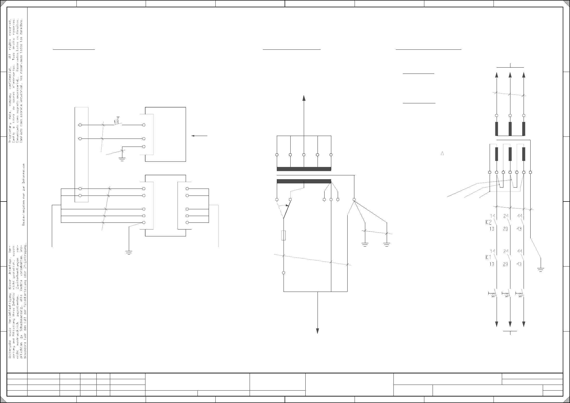
3 Options Circuit Diagrams 101
00117185-010101LD3 Conversion kit 110/208V for SIPLACE 80 S20 / S23 / F4 / F5 (Sh. 3 of 3)
=
Gepr.
Norm
Bearb.
Urspr. Ers. f. Ers. d.Name
SIEMENS AG
+
D
8
B
F
3
A
E
32
D
C
B
L
N
PE
C6A
2,5mm
2
2,5mm
2
1,5mm
2
1,5mm
2
5
C
1 42
54
6
A
7
F
1
87
E
6
1
N
N
1
N
L1
L2
L3
PE
N
L1
L2
L3
PE
C6A
2
1
6
5
4
3
6,3AT / 110V
X1
2
3
1
4
Z1
A1
F1
21
Y501-W1
Y501-W2
.917
X216
6,30AT
110V / 60Hz
10 9 8 7 6
54 321 12
11
Pin5 --> Pin4
1,5mm
2
F1
65
65
208V / 60Hz
G1/G2
2,5mm
2
T1
Y545-W1
Y558-W1
54321
F1
99
W2-V2
U2-V2
V1-U2 ==> BR7
W1-V2 ==> BR6
W2-U1 ==> BR5
99
BR7 BR6 BR5
W2
W1
V2
V1
U2
U1
PE
65
65
65
65
00117185-010101LD3
#
Berger
14.10.1998
10.03.99
14.10.98
14.10.98
01
01.
01
Tek
Wa
Wa
3
3
PL EA1 E2
socket
To
bk
br
bk
bl
gnye
Main power
filter
bk
bl
br
bl
gnye
Main power connector
To
gnye
Plug adapter
br
Adhesive label:
gnye
CO table transformer
Section d):
Service socket
Section c):
gnye
main power switch
Transformer
processor board of component table
To
ground
Table
ground
Cover
WPC power supply unit
Section e):
gnye
bk
bk
bk
rd
rd
rd
rectifier
To
Delta connection
br
bl
gnye
To
power connection power supply infeed
To
Date
Sheet
Sh.
SIPLACE 80 S20 / S23 / F4 / F5 SMD Placement System
for SIPLACE 80 S20 / S23 / F4 / F5
110/208V conversion kit
DateModificationIssue
Document status
Product status
Function status
Service
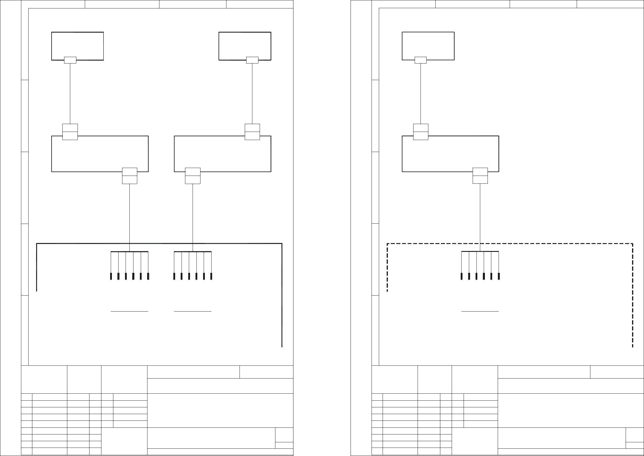
3 Options Circuit Diagrams 102
00116161-020102LD4 Nozzle changer for revolver head S20/F4 (Sh. 1 of 2)
00116161-020102LD4 Nozzle changer for revolver head S20/F4 (Sh. 2 of 2)
A1/X2ka:4
A3/X2kf:-
A3/X2kf:+
A3/X2kf:5
A3/X2kf:6
A3/X2kf:3
A3/X2kf:-
A3/X2kf:+
Nozzle changer
12
wh
br
rd
ye
bl
pk
wh
br
ye
rd
A1/X2ka:3
A1/X2ka:-
Siplace 80S20
bl
pk
nozzle changer
Control board,
X1eb
X1eb
nozzle changer
Control board,
X1ec
X1ec
00317578-02 (W2)
00317353-02
X2ec
X2ec
(ec)
X60
Valve
4321
E
D
C
B
A
Blatt
Datum
Zust Aenderung Datum Name
AUT5-BSM
Siemens AG
Massstab
Bl.
Beab.
Gepr.
Norm
Mat-Nr.:
Function status
SMD Placement System Siplace 80S
Doc. status
1
2
Product status
00321478-03
00317353-02
CAD-Datei:
2.
1.
2.
28.11.96
09.08.95
11616122
09.08.95
00116161-02
terminal strip
Section:
00317578-02 (W1)
(eb)
X2eb
X2eb
X60
Valve
(section: SIPLACE 80S20)
revolver head S20/F4
Nozzle changer for
00116161-020102LD4
Tek
Sz
Sz
08.11.1994
Dax
00317579-01 (W2)
00317579-01 (W1)
A3/X2kf:4
Nozzle changer
A1/X2ka:-
Siplace 80F4
00116161-020102LD4
CAD-Datei:
1.
2.
2.
11616122
28.11.96
09.08.95
Tek
Sz
09.08.95 Sz
(section: SIPLACE 80F4)
revolver head S20/F4
Nozzle changer for
08.11.1994
Dax
00317579-01 (W1)
wh
00116161-02
terminal strip
00321479-04
Section:
A1/X2ka:-
A1/X2ka:4
A3/X2kf:-
A3/X2kf:+
A3/X2kf:5
A3/X2kf:6
Nozzle changer
1
rd
br
ye
bl
pk
Control board,
nozzle changer
00317578-02 (W1)
00317353-02
(eb)
X2eb
X2eb
X60
Valve
X1eb
X1eb
4321
E
D
C
B
A
Blatt
Datum
Zust Aenderung Datum Name
AUT5-BSM
Siemens AG
Massstab
Bl.
Beab.
Gepr.
Norm
Mat-Nr.:
Function status
SMD Placement System Siplace 80S
Doc. status
2
2
Product status