F5HM Circuit Diagrams.pdf - 第117页
4 Printed Circui t Boards 117 0032358 4-010202 ND3 Conver sion board , componen t table Compon ent table con version b oard, SM D SMD placem ent system Siplace 8 0S 00323584-010202ND3
4 Printed Circuit Boards 116
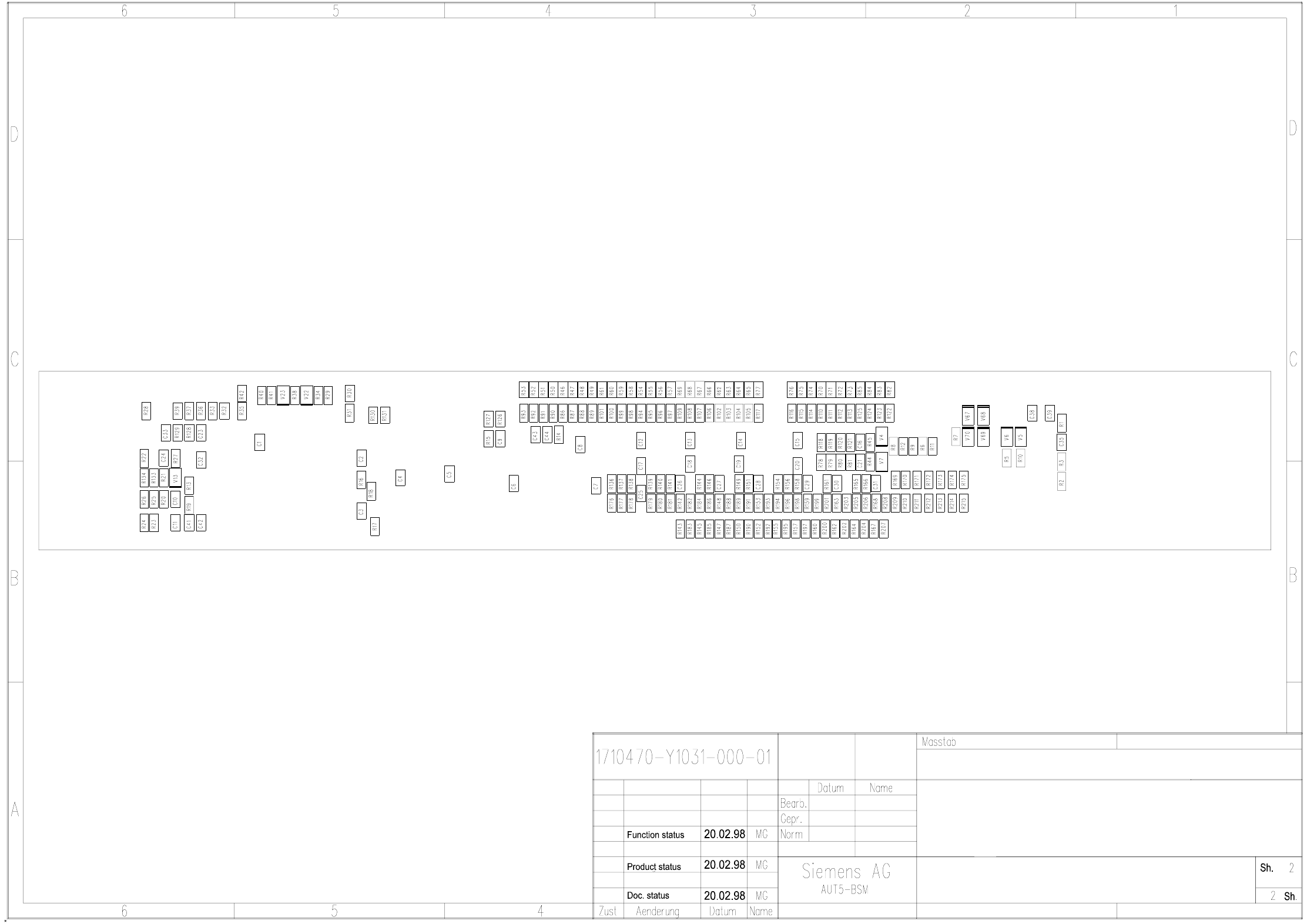
00323583-030101ND3 Control board, component table, (Sh. 2 of 2)
Component table control board, SMD
SMD placement system Siplace 80S
03
00323583-030101ND3
01
01
4 Printed Circuit Boards 117
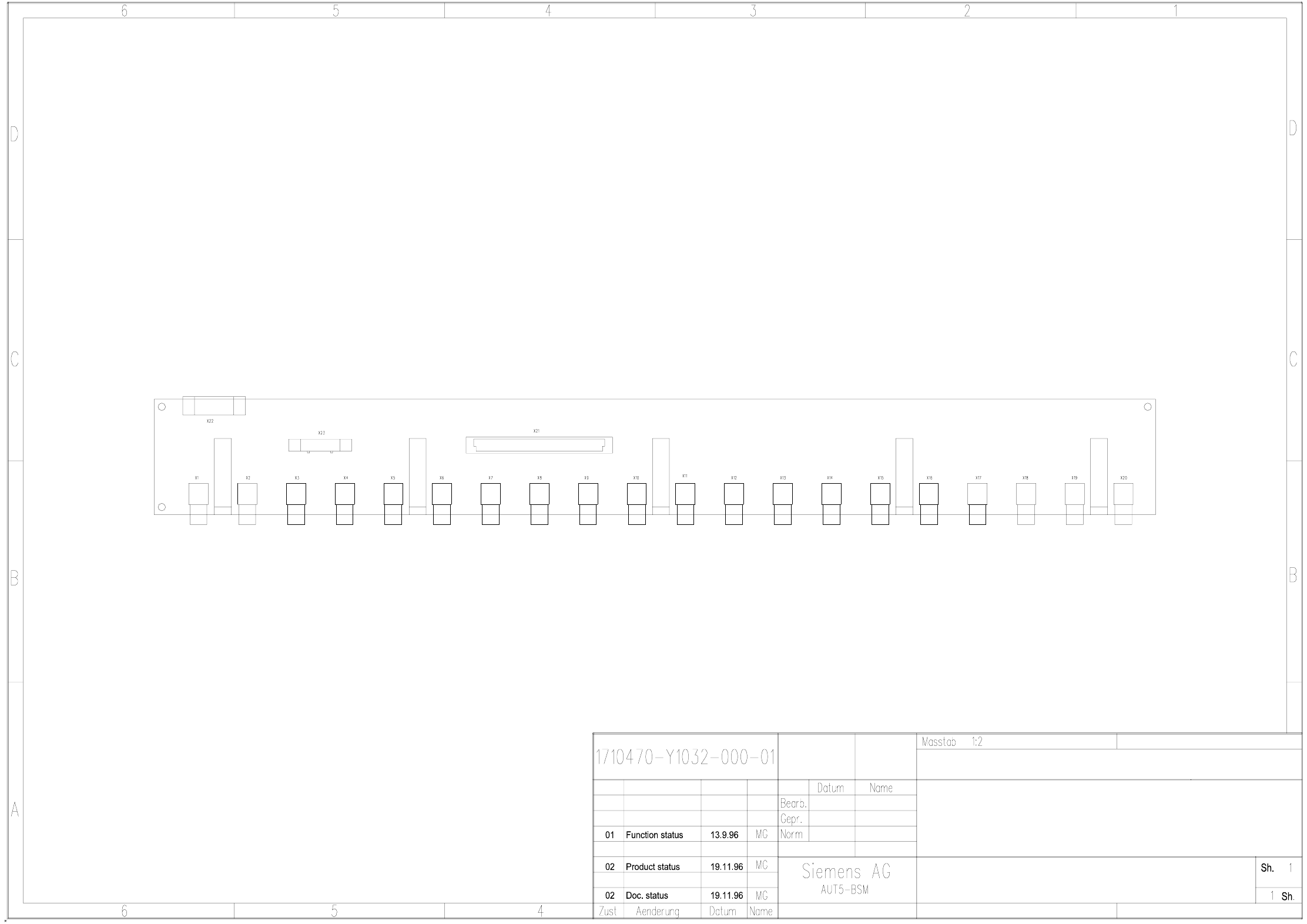
00323584-010202ND3 Conversion board, component table
Component table conversion board, SMD
SMD placement system Siplace 80S
00323584-010202ND3
4 Printed Circuit Boards 118
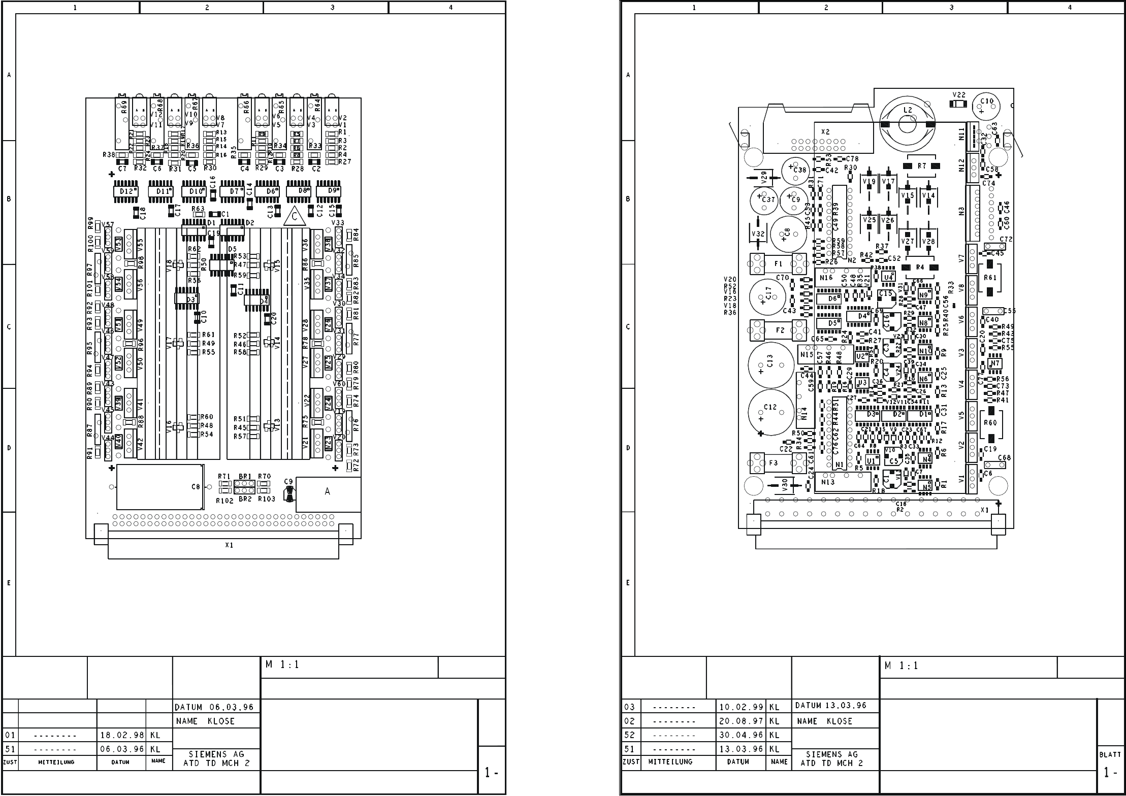
00325460-010101ND4 774 PCB, half bridge board
00325579-020101ND4 775 PCB, step motor control, power circuit
Technische Dokumentation Hick, Technische Dokumentation Hick 18.05.00 10:17 00325460-010101ND4.dwg
A = IDENTIFICATION LABEL
B = INSPECTION LABEL
C = ESD LABEL
B = SOLDER SIDE
PCB 774
HALF BRIDGE BOARD
00325460-010101ND4
G32918-H0005-B001-*-0017
COMPONENT MOUNTING DIAGRAM
4-LAYER PCB
Sheet
P
C
B
775
G
3
2
918-H0006-B001-*-0017
0
0
3
2
5579-020101ND4
C
O
M
P
O
NENT MOUNTING DIAGRAM
4
-
L
A
Y
E
R
PCB
Technische Dokumentation Hick, Technische Dokumentation Hick18.05.00 10:16 00325579-020101ND4_LT.dwg
A = IDENTIFICATION LABEL
B = INSPECTION LABEL
C = ESD LABEL
LABELS A, B, C ON P
L
U
G
X
1
S
T
E
P MOTOR CONTROL
P
O
W
ER CIRCUIT