F5HM Circuit Diagrams.pdf - 第154页
6 WPC 80F/3 154 0032006 4-030101 LD3 Mounti ng plate, g round ter minals ( Sh. 4 of 4) 1.8 0 m 2.5 Ø gnye nderun g Zustand 1. AM 6147 Datum Name 12.06.1 997 Heu Norm Gepr. Heuberg er F. Beab. 25.08.199 2 Datum 123 003200…
6 WPC 80F/3 153
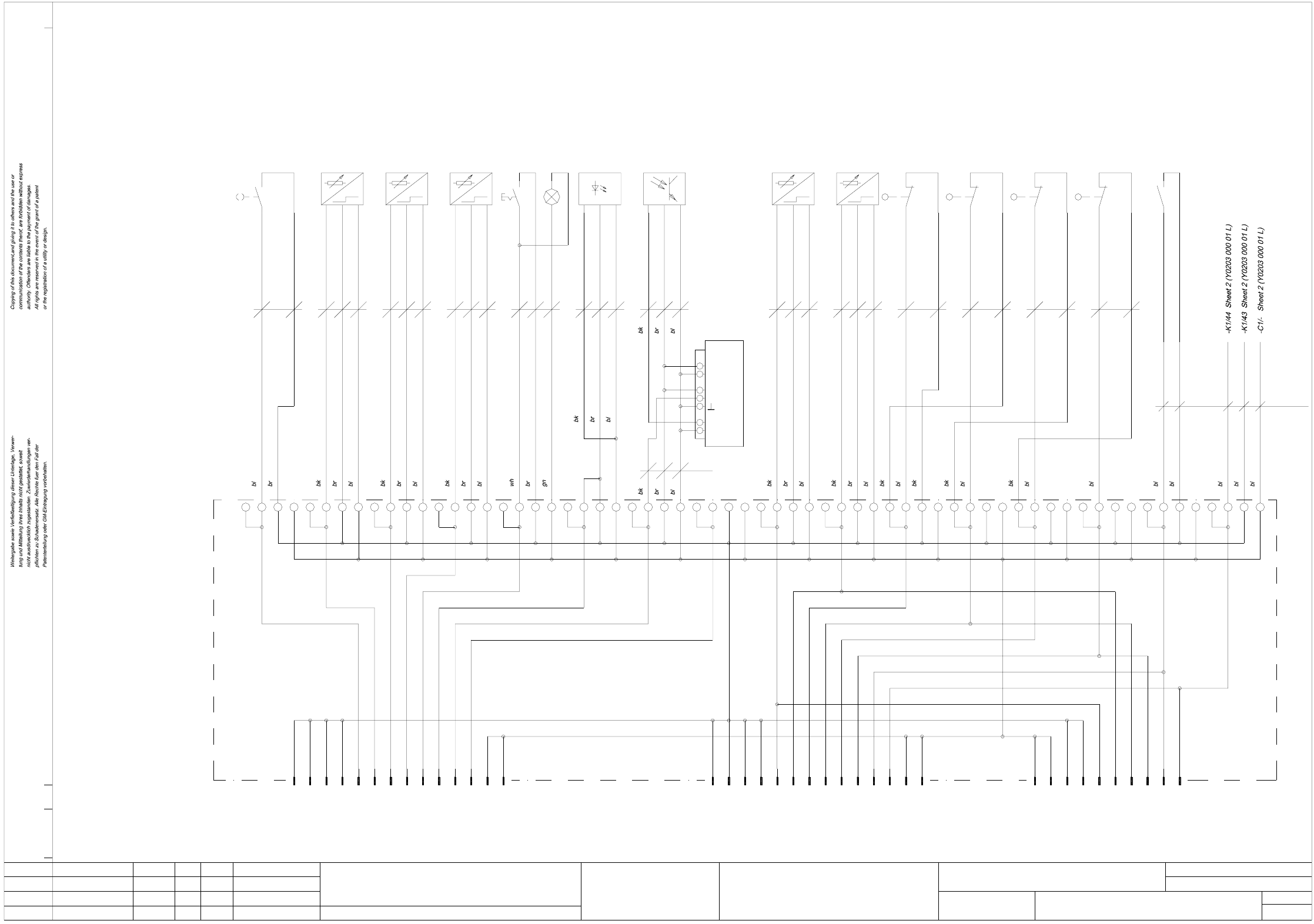
00320064-030101LD3 Mounting plate, distributor inputs (Sh. 3 of 4)
Stromlaufplan/Circuit diagram
8
distributor, inputs
CAD-Datei :
y0203l04_d
Name
Heu
Aenderung
AM 6147
Zustand
1.
Datum
12.06.1997
Norm
Gepr.
Urspr./Ers.f./Ers.d.
AUT 5
8
1
Heuberger F.
Beab.
25.08.1992
Datum
Mat.-Nr. :
2345
A1
-X1
1
4
3
2
7
6
5
SIEMENS
320064
678
Mounting plate
91011
11
10
9
13
12
14
-X2
1
4
3
2
7
6
5
00320064-030101LD3
Sh.
Sh.
15
Wafflepack Changer 80F/3
SIPLACE
12 13 14 16 17 18
10
11
10
9
13
12
14
-X3
8
7
9
6
5
4
2
1
3
+11
-X4
3+223
-- +4+4-- +6+556- +778-- +9+89--
0.14Ø
11+1010 11-+12+12 13-- +14+13 14-16+1515 16--+ -
Setting:
Vcc
Pulse stretching
Ue-
Ue+
Uq
X1
24V
0V
S2=1 20ms
A2
Y203-W17
Y249-W20
14
+A1 A1-
13
Y203-W23
Y203-W18
Y203-W19
Y250-W21
Y203-W11
Y203-W24
T+
+A1+
4b
--
3a
A1 + +A1
-
--
0.75Ø
Y203-W12
Y251-W13
Y252-W14
Y253-W15
Y254-W16
1414
+A1 -
13 13
1414
58
13 13
-K1
57
AY-B3
in storage
Cover closed
Tray
Tray
-S2 AY-B2
ready
(with potentiometer)
Crash light barrier
receiver
Crash light barrier
Locking elem. against rotation
tray
Selector switch
tracks 1-14 slow
Reference point,
feed axis
AY-B4 -S3 AY-B5
transmitter
AY-B6 AY-B1
(motor side)
(operator side)
Reference point,
vertical axis
End position, feed axis 1
End position, feed axis 2
End pos., vertical axis top pos.
End position, vertical axis
Control
activated
Voltage supply
AY-S1BY-B1 AY-S2 BY-S1 BY-S2
24V brake
3
4
bottom position
6 WPC 80F/3 154
00320064-030101LD3 Mounting plate, ground terminals (Sh. 4 of 4)
1.80 m2.5Ø gnye
nderungZustand
1.
AM 6147
Datum Name
12.06.1997
Heu
Norm
Gepr.
Heuberger F.
Beab.
25.08.1992
Datum
123
00320064-030101LD3
CAD-Datei :
y0203l04_d
Stromlaufplan/Circuit diagramUrspr./Ers.f./Ers.d.
AUT 5
Mat.-Nr. :
320064
456
SIEMENS
78910
(5) Mark with ground point
Mounting plate
ground terminals
11 12 13
Wafflepack Changer 80F/3
SIPLACE
14 15 16
Sh.
Sh.
17 18
(4) Flat plug sleeve 6,3
(3) Fork cable lug M6
(1) Annular cable lug M5
(2) Annular cable lug M4
1.20 m2.5Ø gnye
2.5Ø gnye
2.5Ø gnye 0.65 m
1.10 m
2.5Ø gnye
2.5Ø gnye
0.55 m
0.80 m
Cover plate, EMERG.-STOP button(4)
Front cover plate (operator side)
(4)
Cover plate, motor, vertical axis(4)
(5)
(5)
(5)
(4)
Cover plate, righthand side(4)
Cover plate, lefthand side
Y201-X2 / ground, control unit
(3)
(5)
(5)
2.5Ø gnye 1.00 m
2.5Ø gnye 0.70m
2.5Ø gnye 0.15m
0.20 m2.5Ø gnye
2.5Ø gnye
1.5Ø gnye
2.5Ø gnye 1.60 m
Y203 G1/-
Transformer -T1
Y203 mounting plate
(2) (5)
Y201 rear panel, casing, control unit
Y201 casing, control unit, door(4)(2)
(4)
Magazine cover(4)
(5)(5)
(5)
(5)
gnye
2.5Ø gnye
PE
0.55 m
gnye
Y203-W4 power supply, control unit
Machine rack
(1)
Y241-W1 infeed
(5)
4
4
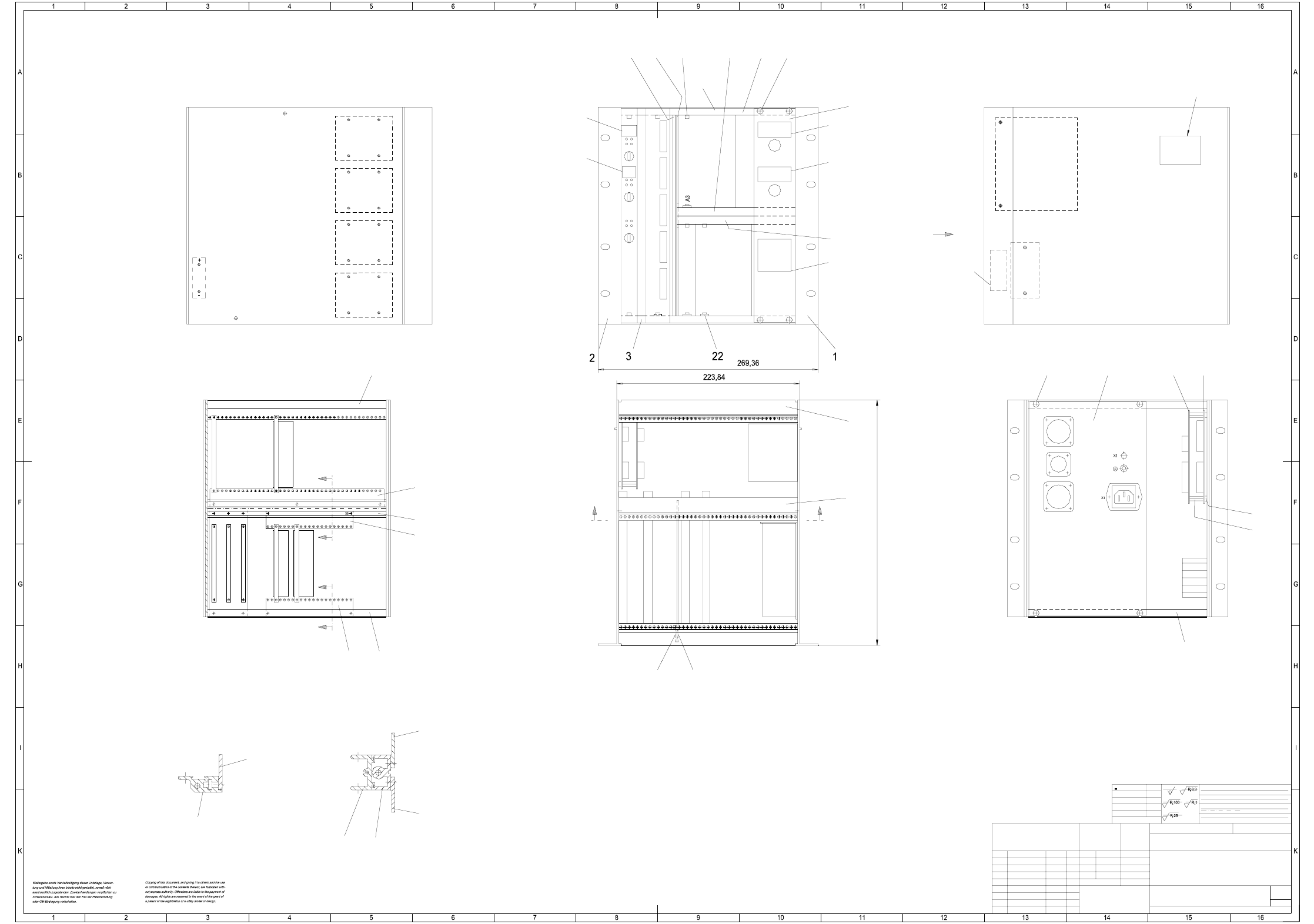
6 WPC 80F/3 155
00302827-020101ZD1 Control unit / servo unit
321 45678910
17
K.Brunner04.02.93
1:2
SIPLACE WPW80F/3
Control unit / servo unit
00302827-020101ZD1
FS 02 AM 5983 10.03.97 Draeg
2-5 um chemisch vernickelt
Tiefe:0,3/
1710xxx Xxxxx xxx xx P
A1
1
mittel
NN ± N
Inscription label
X4
Encoder, lift axis
X3
Encoder, feed axis
X5
X9
Fan
Inputs,
axis board
Sheet
Sh.
X3
X2
X1
A7
SMP bus
21
18
Feed axis
Servo controller, feed axis
A4
Servo controller, lift axis
A5
Ballast circuit, lift axis
Ballast circuit
19
20
Designation label
Section: C-C
M 1:1
M 1:1
Section: A-A
Section: B-B
strip
Inscription strip
Inscription label
Inscription label
Inscription label
Inscription label
Inscription label
Hierzu gehoert
Koordinatenliste:
(Werkstoff,Halbzeug)
(Rohteil-Nr)
(Modell- oder Gesenk-Nr)
Format
(Zeichnungsnummer)
Massstab
Norm
Gepr.
Bearb.
Datum Name
einsatzgehaertet
gehaertet HRc
Oberfl.:
±0,8
±0,5
±0,3
±0,2
±0,1
>400...1000
>120...400
>30...120
>6...30
<6
Freimasstoleranzen
NameDatumMitteilungZustand
AUT 5
SIEMENS
Freimaátoleranzen:
Genauigkeitsgrad
nach ISO 2768 mH
Stamm-Nr. FS ES USUAS F
13
1
A6
Power supply unit +5V,ñ15V,+24V
Guide rail in hole 21/22
Guide rail in hole 16/17
Guide rail in hole 7/8
Guide rail in hole 1/2
Inscription
Discharge time
2 minutes
A8
17
X14
Output byte
X12 X13
Input byte 1 Input byte 2
A2
V24 SIPLACE
V24 terminal
X11X10
Feed
axis
Lift
axis
A1
9
3
9
8
76
"X" view
X
C
C
B
B
A
A
X8
Motor, lift axis
X6
Motor, feed axis
X7
Power supply, servo
Main power connector
220/110V
E1
Battery
A12
S2
Brake
release
S1
Limit switch,
lift axis
A11
A9
A10
14
Inscribed directly onto pos. 914
Ground
17
22
A8
+5V
0V
+15V
-15V
L1-L4
L4
L3
L2
L1
12
(12)
11
(11)
14
(3)
(3)
(3,10)
5
(9)
9
8
5
6;7
4
15,16
(15,16)
(10)
300
6 15102