F5HM Circuit Diagrams.pdf - 第70页
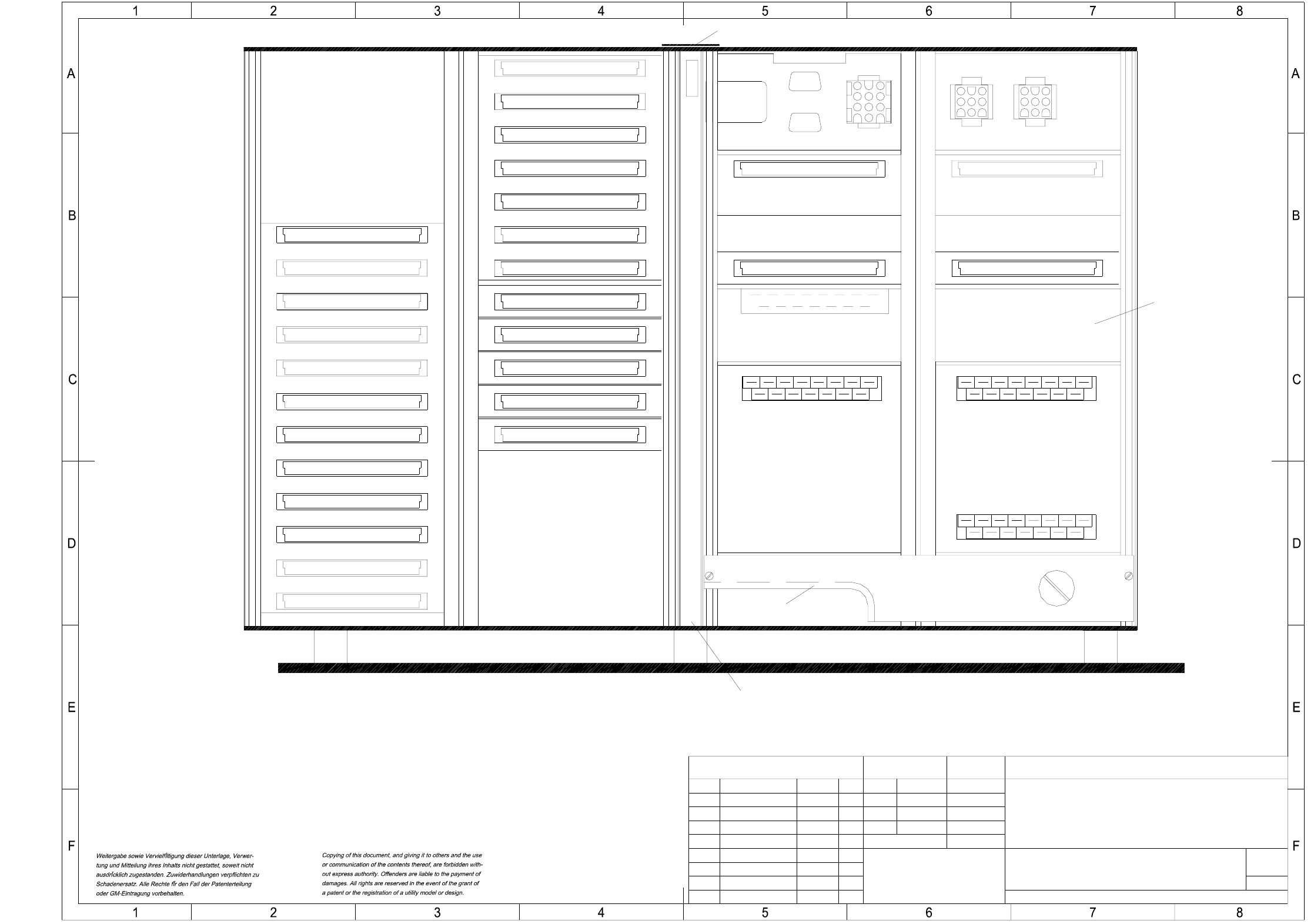
2 Circuit Diagr ams 70 0034518 0-010101TD3 F5 HM control un it without MVS (vie wed from t he front) ( 015 ) incl. H15 se ction Part of 6HE- 44,5 fr ont p late X98 X18 X19 X17 X21 X20 X1rz X2rz X3rz X4rz X121 X120 Edge p…
2 Circuit Diagrams 69
00345180-010101LD3 F5 HM control unit without MVS
=
Datum
Gepr.
Norm
Bearb.
Sheet
Urspr. Ers. f. Ers. d.NameDatumAenderungZustand
SIEMENS AG
Sh.
+
8
X98
wh
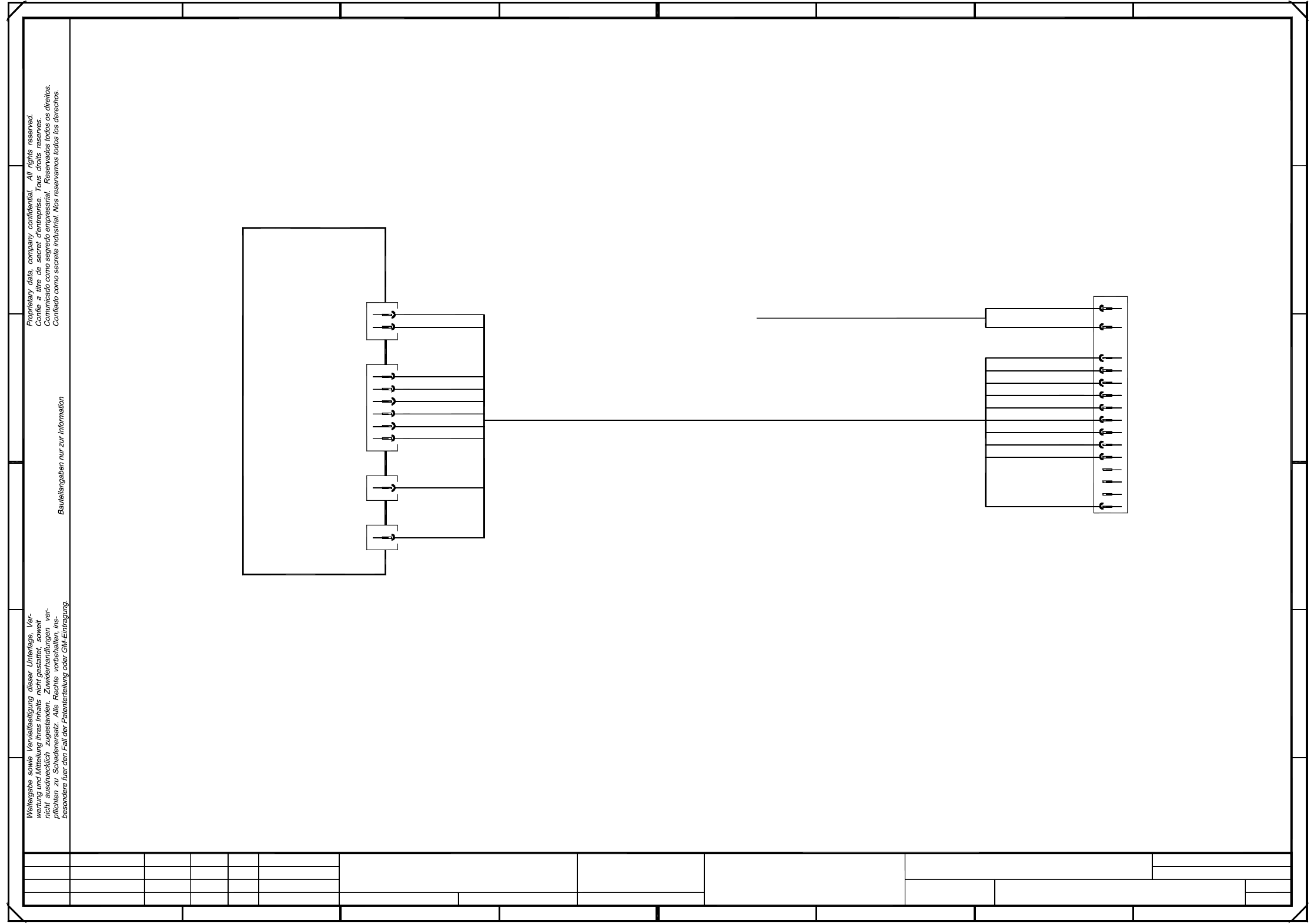
00336795
Cable: coplanarity module - terminal panel
Connect both wires
from X211 to pin 21
To
(lefthand side)
terminal panel
wh
bn
Backplane
power ( ts )
Cable harness for the coplanarity module
Please note:
The cable harness for the coplanarity module is to be integrated in the internal cable harness for the control unit!
6
wh
bn
wh
A
+5V
+5V
+24V
B
D
+12V
0V
C
0V
0V
0V
0V
pk
pk
wh
wh
wh
wh
wh
wh
bn
rd
57432
D
C
B
1234567
wh
rd
+5VDC
SMD Placement System SIPLACE 80 F5-HM
0V
1
E
F F
E
wh
pk
pk
wh
A
8
0V
+24VDC
+12VDC
10
1
1
Tek
Tek
Tek
01.
01.
01.
Function status
Product status
Document status
02.11.99
02.11.99
02.11.99
02.11.1999
Tekin
#
F5-HM control unit without MVS
00345180-010101LD3
PL EA1 E2
12
14
4
6
8
16
18
20
22
24
26
28
30
32
supply
2 Circuit Diagrams 70
00345180-010101TD3 F5 HM control unit without MVS (viewed from the front)
( 015 )
incl. H15 section
Part of 6HE-44,5 front plate
X98
X18X19
X17
X21
X20
X1rz
X2rz
X3rz
X4rz
X121X120
Edge protection
MVS backplane
A27
Power supply unit
X25
X24
X23
X99
A36
X5rz
X22
AMS bus board
X7rz
X6rz
A32
SMP bus board
X10su
X9su
X8su
X7su
X6su
X5su
X4su
X3su
X2su
X1su
010
A33
X9sv X8sv
X3ts
X1ts X2ts
Fan unit A35 (ue)
X1ue
Stay bar
X12su
X11su
3.8V
Battery
1
neu Tek
Tekin01.10.1999
Massstab
1:2
1
A3
(viewed from the front)
F5-HM control unit without MVS
SMD Placement System SIPLACE S23-HM
US 01 01.10.99
01.10.99
00345180-010101TD3
FSUAUSESFSStamm-Nr.
SIEMENS
PL EA 1 E2
Zustand Mitteilung Datum Name
Name
Datum
Bearb.
Gepr.
Norm
(Drawing number)
Sh.
Sheet
backplane
2 Circuit Diagrams 71
00342581-040101FD4 F5 HM control unit, base (wrap connections) (Sh. 1 of 3)
00342581-040101FD4 F5 HM control unit, base (wrap connections) (Sh. 2 of 3)
6LHPHQV$*
:UDSFRQQHFWLRQV
'UDZLQJQXPEHU )'
'HVLJQDWLRQ 6+0FRQWUROXQLWEDVH
3/($(
5HVSRQVLEOH3/($(5HI
:ROOJDUWHQ
6LJQDWXUH 7HVWGHSDUWPHQW 'HYHORSPHQWGHSDUWPHQW 3DJH RI
'DWH
S23 Control Unit, Wrap connections incl. M54
(AMS bus with 7 slots)
Coding, axis board 1 (SP3):
Axis no. 0 (module 1)
Axis no. 1 (module 2)
Axis no. 2 (module 3)
SMP-SP3 connection:
B7
⇔
B16
⇔
B19
Coding, axis board 2 (SP4):
Axis no. 3 (module 1)
Axis no. 4 (module 2)
Axis no. 5 (module 3)
SMP-SP4 connection :
B3
⇔
B4
⇔
B9
⇔
B16
⇔
B18
⇔
B20
Coding, axis board 3 (SP5):
Axis no. 6 (module 1)
Axis no. 7 (module 2)
Axis no. 8 (module 3)
SMP-SP5 connection :
B4
⇔
B5
⇔
B7
⇔
B8
⇔
B9
⇔
B16
⇔
B21
Coding, axis board 4 (SP6):
Axis no. 9 (module 1)
Axis no. 10 (module 2)
Axis no. 11 (module 3)
SMP-SP6 connection :
B3
⇔
B6
⇔
B8
⇔
B10
⇔
B16
⇔
B18
⇔
B19
⇔
B21
AMS interrupt axis boards
Connections:
AMS-SP6 / C7
⇔
SMP-SP3 / C15
⇔
SMP-SP3 / C17
⇔
SMP-SP3 / C19
⇔
⇔
SMP-
SP4 / C15
⇔
SMP-SP4 / C17
⇔
SMP-SP4 / C19
(AMS_INT2)
AMS-SP6 / A8
⇔
SMP-SP5 / C15
⇔
SMP-SP5 / C17
⇔
SMP-SP5 / C19
⇔
⇔
SMP-SP6 / C15
⇔
SMP-SP6 / C17
⇔
SMP-SP6 / C19
(AMS_INT3)
Coding for I/O boards 1 - 3 (SP8 - SP10):
Connections:
I/O board 1 SMP-SP8 / C31
⇔
SMP-SP8 / C23
⇔
⇔
SMP-SP8 / C25
⇔
SMP-SP8 / C27
I/O board 2 SMP-SP9 / C31
⇔
SMP-SP9 / C23
⇔
⇔
SMP-SP9 / C25
I/O board 3 SMP-SP10 / C31
⇔
SMP-SP10 / C23
⇔
⇔
SMP-SP10 / C27