F5HM Circuit Diagrams.pdf - 第78页
2 Circuit Diagr ams 78 0034582 2-010101 LD3 Circui t diagram, F5 HM bas e (Sh. 1 of 4) = Datum Gepr. Norm Bearb. Sheet Urspr. Ers. f. Ers. d. Name Datum Aenderung Zusta nd SIEME NS AG Sh. + X11d X2va Servo Dyn. brake 3 4…
2 Circuit Diagrams 77
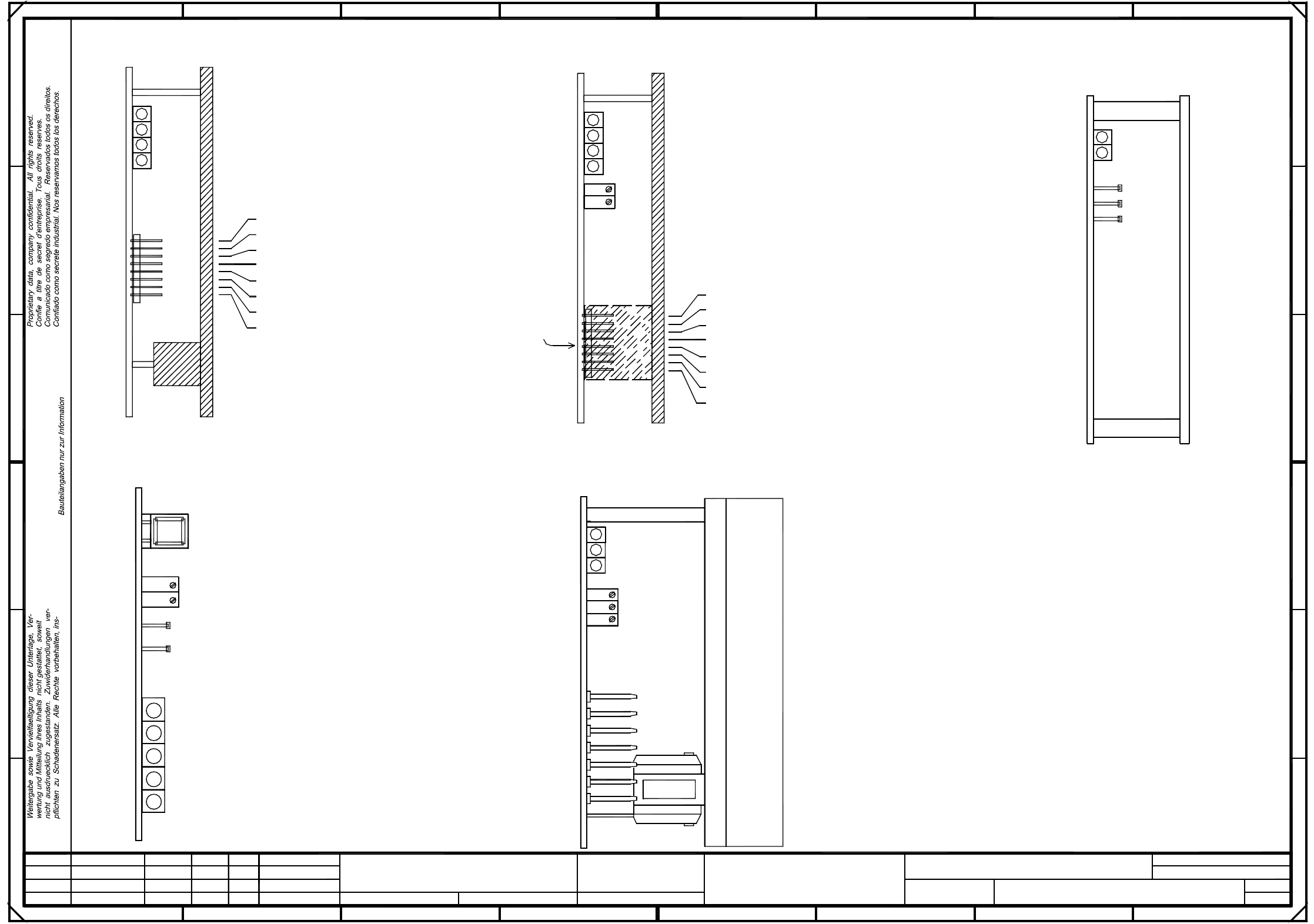
00345821-010101TD3 Assemblies overview (Sh. 2 of 2)
Anti-crash board
Distance sensor
-15V
GND
+15V
5
456
-15V
Offset
Servo card, star axis,
Tacho
P gain
Fault
Ready status
I r.m.s. limiting (I2xt signal)
Power supply unit
F
21
TBS120/2,5S
Ss Sensor stop signal
0V Amplifier electronic, GND
IA Motorstellgroesse (current controller output)
Is Current nom. value (speed control output)
Ta Tachometer (actual tachometer voltage)
TDS 120A 2,5Z
2
x t signal)
Note:
C
D
Reset button
Zero point, distance sensor
TDS120/1D
Fault
Ready status
Output stage, enable
Servo card, DP1-axis,
Servo card, Z-axis,
P gain
10V correspond
Scaling:
to max. motor
Y-axis, gantry II
NS Nominal speed
0V amplifier electronic, GND
3
Usoll(U) Current reg. output
Iist(W) Current actual value
Iist(U) Current actual value
10.02.99
Tuth
#
(Assembly overview)
00345821-010101TD3
10.02.99
10.02.99
PL EA1 E
}
}
Ns Nominal speed
Ii Current actual value
Analog voltage, distance sensor
AGND
and Y-axis, TBF 120/12 TS
SIPLACE 80F5-HM
Deu
Deu
Deu
01
01
01
Function status
Product status
Document status
10.02.99
Heat sink installed for Z-axis only
+15V
E
Iu Current monitor, phase U
X-axis, gantry II
E
D
C
B
A
876
B
A
2
besondere fuer den Fall der Patenterteilung oder GM-Eintragung.
X-axis, gantry I
FD Fault diagnosis
Servo card, X-axis, TBF 120/7 TS
Y-axis, gantry I
Amplification, distance sensor
F
Ni Actual speed
Tachometer
I r.m.s. limiting
Ie Nominal power input
(I
Is Current, nominal value (output, speed control)
Iv Current monitor, phase V
4321
SMD Placement System
2
87
Scaling:
of device
to max. current
Is(W) Current nom. value
Is(U) Current nom. value
Usoll(W) Current reg. output
Spare
0V Reference potential
+
Sh.
SIEMENS AG
Zustand Aenderung Datum Name Ers. d.Ers. f.Urspr.
Sheet
Bearb.
Norm
Gepr.
Datum
=
Output stage, enable
I r.m.s. limiting
Fault
(I²
Ready status
x t signal)
10V correspond
voltage
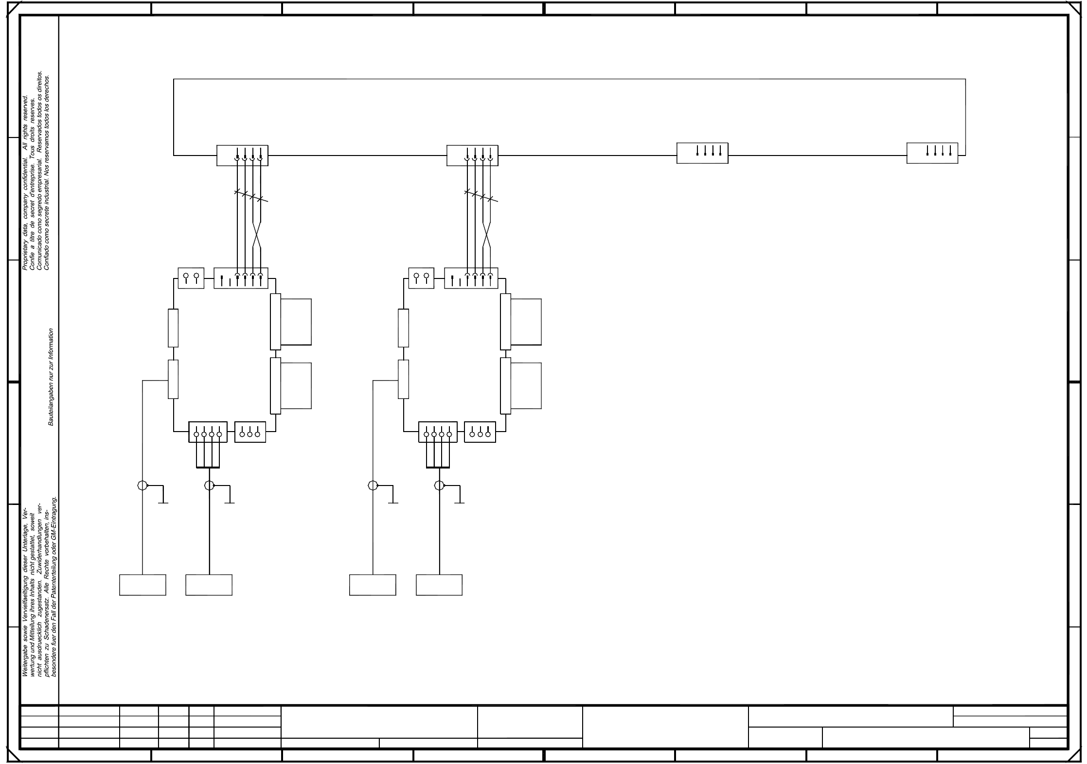
2 Circuit Diagrams 78
00345822-010101LD3 Circuit diagram, F5 HM base (Sh. 1 of 4)
=
Datum
Gepr.
Norm
Bearb.
Sheet
Urspr. Ers. f. Ers. d.NameDatumAenderungZustand
SIEMENS AG
Sh.
+
X11d
X2va
Servo
Dyn.
brake
34
X4vaX5va
00346382-xx
00346381-xx
(va)
+15V
21
-15V
Ready
Tacho
GND
Key
Axis cardTacho/RSE
Backplane
X-axis
Motor W
Power GND
Motor U
12
X7vbX7va
(vb)
1
3
412
4
X11b
X11c
X5vb
X2vbX1vb
X3vbX6vb
X11a
23
X6va X3va
X1va
3
00346384-xx
00346383-xx
Backplane
Y-axis
A14
2
+15V
-15V
1
2
SMD Placement System
1
Motor V
1
234
Axis cardTacho/RSE
123
Motor U
Power GND
Power +Ub
Power GND
Servo
A13
Power GND
Power +Ub
Motor V
Power GND
Dyn.
Tacho
Ready
+15V
34
X4vb
2
X8va
654 8
+15V
brake
12
3
4
1
4
X8vb
1
Anti-crash card A12
0,25mm²
1234 1
ye/bk
34
GND
1
ye/bk
A
Motor W
Power GND
1
Key
4
E
D
C
B
A
2
78
D
E
FF
bl
br
00337333-01
ye/gn
bk
0,25mm²
7
SIPLACE 80F5-HM
6
ye/gn
bk
32
X32a X31a
Deu
Deu
01
01
01
Function status
Product status
Document st.
10.02.99
10.02.99
10.02.99
10.02.99
Tuth
#
Circuit diagram
00345822-010101LD3
bl
br
5
X38aa X36aa
B
C
23
PL EA1 E
Deu
F5 HM servo unit, base
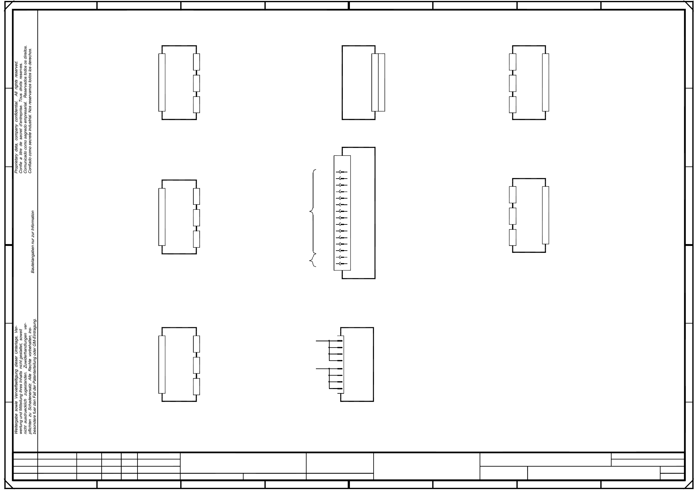
2 Circuit Diagrams 79
00345822-010101LD3 Circuit diagram, servo unit (Sh. 2 of 4)
Deu
PL EA1 E
A
456723
B
00345822-010101LD3
Circuit diagram, servo unit
#
Tuth
10.02.99
10.02.99
10.02.99
10.02.99
Document status
Product status
Function status
01
01
01
Deu
Deu
12
10
8
6
4
X12
Power supply unit
(+/-15V)
A12
Backplane
+15V
Nominal values
Motor
Tachometer
Voltage
X1vk
X3vk
1
E
F F
E
D
C
B
6
2
D
SMD Placement System
SIPLACE 80F5-HM
Input
Output
6L+
1L-
-15V
-15V
-15V
-15V
-15V
-15V
1L-
+15V
+15V
z-axis, IC head
+15V
+15V
+15V
32
30
28
26
24
22
20
18
16
14
Voltage
X1vg
X3vg X2vgX4vg
3L+
A18 (vg)
Nominal values
Motor
Tachometer
Voltage
DP1-axis
(Gantry 1)
Backplane
X1vf
3L+
A15 (vf)
X2vf
A
54321
8
4
C
87
X4vd
Nominal values
Motor
Tachometer
Voltage
Star
(Gantry 1)
Backplane
X1vc
2L+/5L+
A17 (vc)
X2vcX3vcX4vc
150V
c8
c6
c4
X2vkX4vk
3L+
A19 (vk)
X11
Anti-crash card
X1
A10
Backplane
DP1-axis, IC head
Nominal values
Motor
Tachometer
c2
GND
X13
a8
a6
a4
a2
Ballast circuit
A11
X3vfX4vf
Nominal values
Motor
Tachometer
Voltage
z-axis
(Gantry 1)
Backplane
X1vd
3L+
A16 (vd)
X2vdX3vd
+
Sh.
SIEMENS AG
Zustand Aenderung Datum Name Ers. d.Ers. f.Urspr.
Sheet
Bearb.
Norm
Gepr.
Datum
=